
Prerequisites
Atmospheric distribution system (see Life Support I)
Adequate gas supply for container storage
Objectives
Automatically recharge EVA suits (battery, gases, exhaust removal)
Deliver gases to equipment using portable canisters instead of permanent pipes
Constraints
Portable canisters must survive fire conditions up to 300°C (fuel mixtures excluded due to combustion risk)
Canister charging stations must be able to safely support both standard canisters and smart canisters
Need a way to reintegrate unused gases back into the atmospheric recovery unit
Materials and Components
Fabricated Components
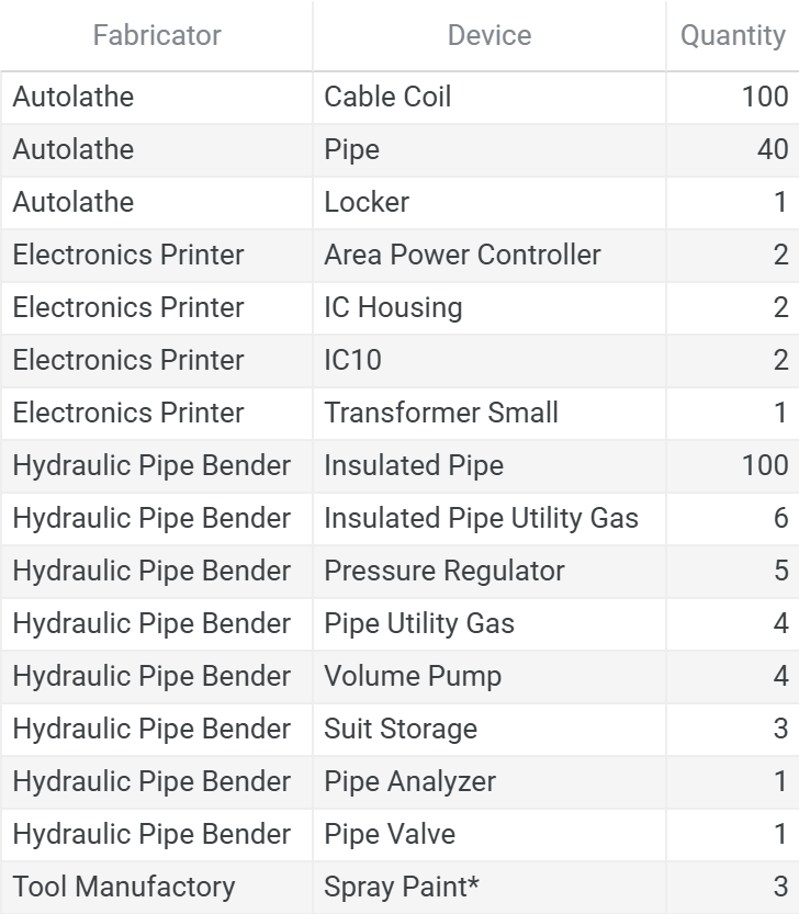
* Spray Paint Colors: 1 Black, 1 White, 1 Gray
Total Ingots
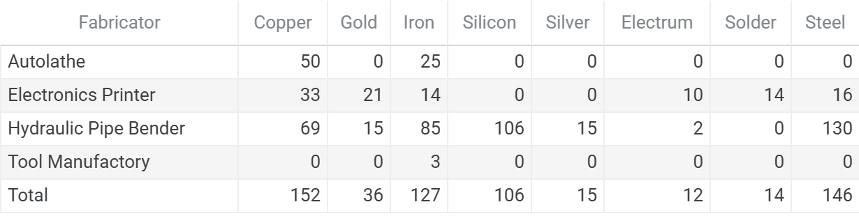
Raw Ores
This chart format is standardized across the series. See the full legend in Atmospheric Recovery on the Moon, Appendix A11. Bill of Materials.
Ores:

- Coal    -  2 stacks
- Copper  -  4 stacks
- Gold    -  4 stacks
- Iron    - 12 stacks
- Lead    -  1 stack
- Silicon -  3 stacks
- Silver  -  3 stacks

Ingots:

- Copper →
  - Copper: 1/1/2/0
- Gold →
  - Gold: 0/1/1/0
- Iron →
  - Iron: 1/1/2/1
- Silicon →
  - Silicon: 0/0/3/0
- Silver →
  - Silver: 0/0/1/0
- Electrum →
  - Gold:   0/1/1/0
  - Silver: 0/1/1/0
- Solder →
  - Iron: 0/1/0/0
  - Lead: 0/1/0/0
- Steel →
  - Coal: 0/1/1/0
  - Iron: 0/3/3/0
Power Infrastructure
Portables systems operate on a dedicated power hierarchy within the zone network, enabling independent fault isolation and priority management.
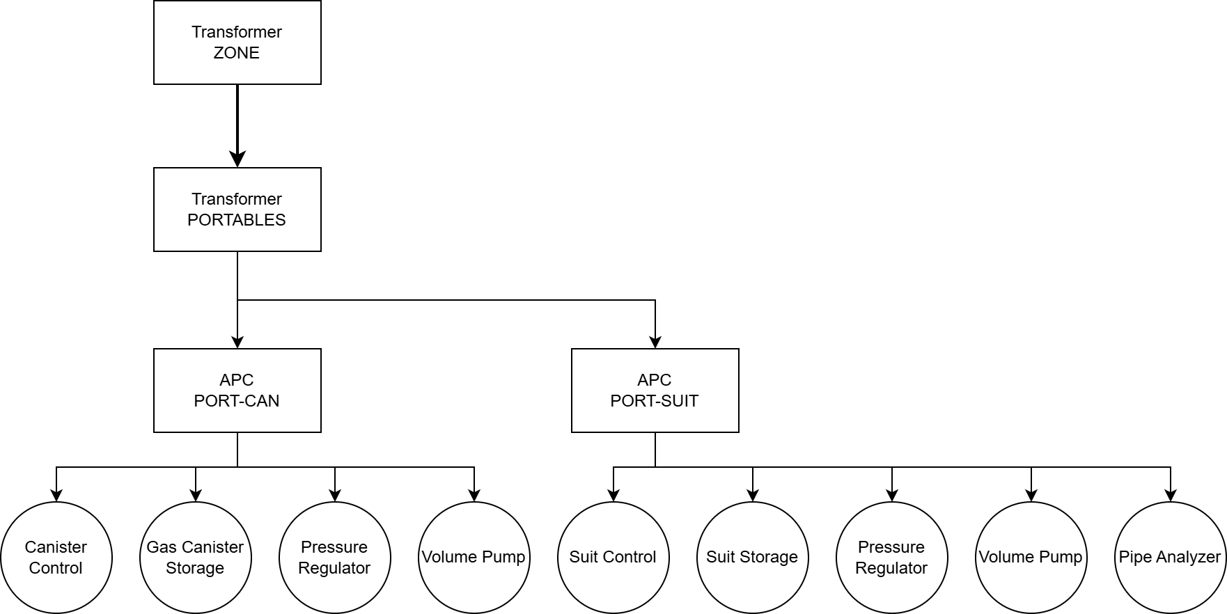
The portables transformer (2667 W) feeds two isolated APCs:
PORT-SUIT — Suit storage operations (battery charging, gas refills, exhaust evacuation)
PORT-CAN — Canister fill and evacuation
Emergency Power
The PORT-CAN APC accepts an optional backup battery, enabling emergency canister fills during power outages or transformer failures. This ensures critical gas delivery capability remains available when primary power is unavailable.
Power Budget
Operations complete in under one minute each, with total active with time budgeted at 60 seconds per lunar day (218 kJ). Controller idle power (100 W continuous) represents the primary ongoing draw.
Parallel Construction Tracks
This build consists of two independent construction tracks that can be completed in any order based on priorities and available construction time.
Track Overview:
Suit Storage - Automated system for recharging suit batteries, refilling breathing (O2) and propellant (N2) gases, and evacuating exhaust tanks. Processes up to 6 suits sequentially to minimize power load
Canister Fill Station - Gas filling and evacuating infrastructure for portable canisters. Supports configurable gas types (O2, N2, CO2) with automatic canister detection and exhaust recovery to atmospheric processing.
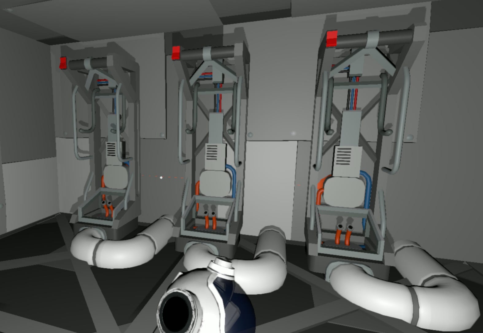
Track 1: Suit Storage
This build provides infrastructure to support three suit storages. A single controller can manage up to 6 suit storages, so this configuration leaves room for future expansion. Operators can adjust the installation based on their use case—adding or removing suit storages by replicating the gas supply and exhaust pipe connections without modifying the core architecture.
Exhaust Removal Formulas
The exhaust system uses a two-stage approach, similarly seen in Life Support I: Base Pressure and Composition: rapid internal evacuation to a buffer tank, followed by controlled external evacuation to the ECL (Exhaust Capture Line). This protects vulnerable walls and surfaces from burst events while maintaining efficient suit processing.
Buffer Volume Sizing
The suit storages’ inward lines connect to a minimum 640 L volume to ensure that gases are safely evacuated regardless of bottlenecks in the ECL pipe network:
Where:
Vbuffer = buffer volume (L)
Vcanister = canister volume (64 L)
Pcanister_max = maximum canister pressure (20,265 kPa for smart canisters)
Pmax = 50,662.5 kPa (90% structural limit - operational high watermark)
Psafety = 48,636 kPa (80% structural limit - pump activation threshold)
Pump Rate Calculation
When buffer pressure exceeds the safety threshold, volume pumps with a 25.6 L/tick capacity activate to evacuate the local inward pipe. Maximum pump rate:
The system preferentially uses passive drainage (directional valve) and activates pumps only when necessary to prevent overpressure in wall penetrations.
Components Required
1 Area Power Controller
1 IC Housing
1 IC10
3 Suit Storage
2 Pressure Regulator
3 Volume Pump
1 One-way Valve (Pipe Valve Kit)
1 Pipe Analyzer
2 Spray Paint (White, Black)
~6 Insulated Pipe Utility Gas
~40 Insulated Pipe
~20 Pipe
~50 Cable Coil
Color Coding System
Paint atmospheric infrastructure based on gas type:
Gray - Carbon Dioxide
Black - Nitrogen (propellant)
White - Oxygen (breathing)
Orange - Exhaust
Installation Steps
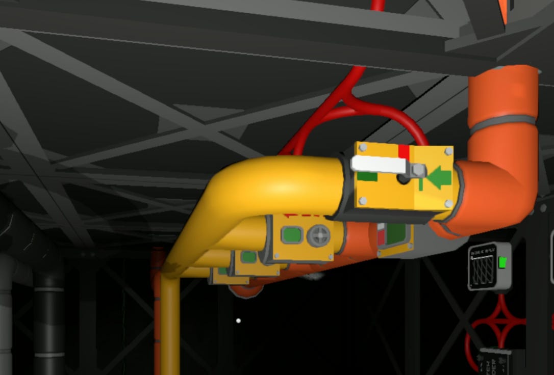
Install pipe connections for oxygen, nitrogen and exhaust on the exterior wall. Nitrogen is flush to the floor of the base. Exhaust is right above the nitrogen line, and oxygen is to the side of the nitrogen line.
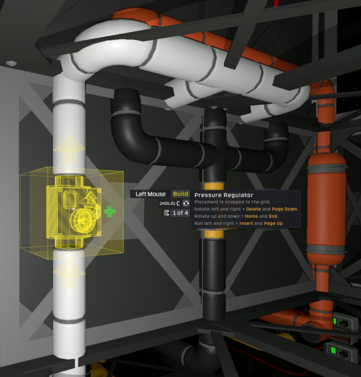
Connect pressure regulators to the oxygen and nitrogen lines.
Connect and open the directional valve and attach pumps along the exhaust line to feed into the ECL.

Along the interior wall, install suit storages so that the nitrogen and exhaust pipes connect directly to the back of each unit. Snake the oxygen pipe so that it connects to the front port.
Cabling
Attach area power controller and IC housing and connect cables to
APC output
IC Housing (power and data)
Suit Storages (power and data)
Pressure Regulators
Volume Pumps
Pipe Analyzer
APC input will feed power from the PORTABLES transformer.
Configuration
Use the labeler to assign the following device names:
Pressure Regulators:
PortableOxygenPortableNitrogen
Exhaust Equipment:
Pipe analyzer, Volume Pumps:
PortableExhaust
Track 2: Canister Fill Station
This build provides infrastructure to support oxygen, nitrogen, carbon dioxide fills, and exhaust removal. The controller supports up to six configurable outward lines plus a dedicated exhaust line. All feed lines operate simultaneously, with fills automatically stopping at pre-defined pressure limits (hard-coded) based on canister type detection.
Fire-Safe Pressure Limits
Maximum fill pressures are calculated to ensure canisters remain below rupture thresholds even when heated to autoignition temperature (573.15 K) during fire scenarios:
Where:
Pburst = canister pressure rating (10,132.5 kPa standard, 20,265 kPa smart)
Tautoignition = 573.15 K (300°C - material autoignition temperature)
Tmin = 293.15 K (20°C - minimum expected line temperature)
Calculated Limits
Standard Canisters: 10,132.5 × 293.15 / 573.15 = 5,182 kPa
Smart Canisters: 20,265 × 293.15 / 573.15 = 10,364 kPa
These limits provide thermal safety margin, ensuring canisters can withstand fire exposure without rupture even during extended heating.
Components Required
1 Area Power Controller
1 IC Housing
1 IC10
4 Gas Tank Storage
3 Pressure Regulator
1 Volume Pump
3 Spray Paint (Gray, White, Black)
~60 Insulated Pipe
~20 Pipe
~50 Cable Coil
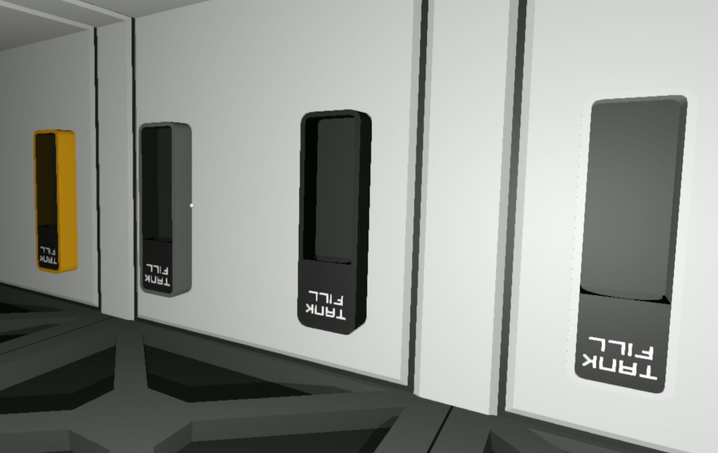
Installation
Attach Gas Tank Storages to wall surfaces, with each storage connected to a 10L pipe segment.
Connect pressure regulators to outward gas supply lines (O2, N2, CO2), oriented with flow direction pointing toward the Gas Tank Storages.

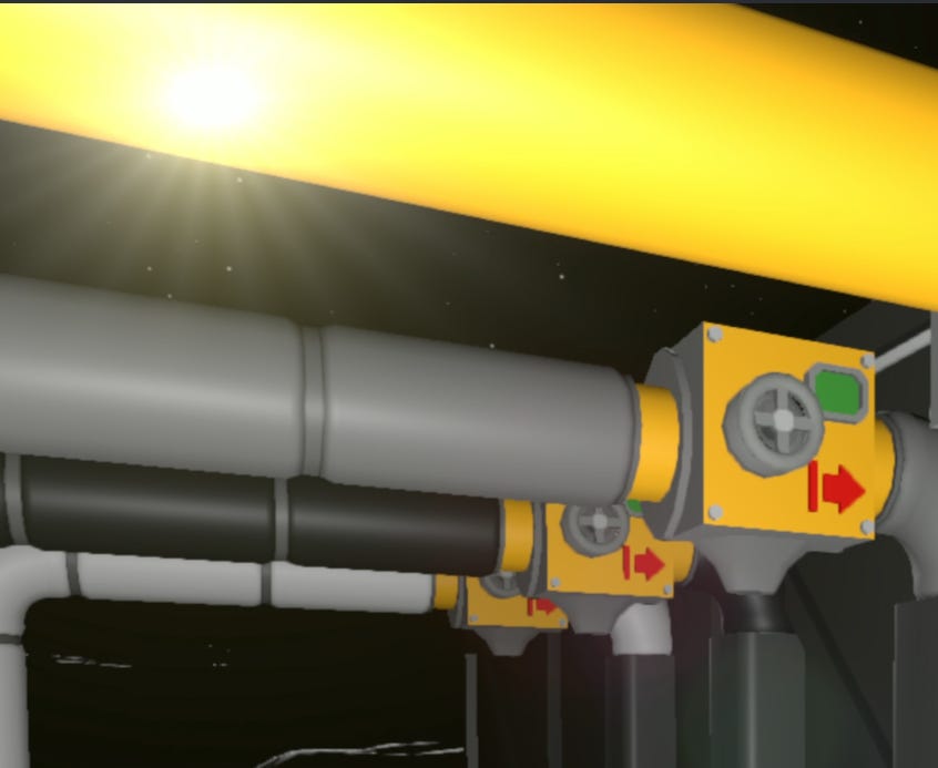
Connect a volume pump to the exhaust line, oriented with flow direction pointing away from storage toward the ECL.
Cabling
Attach area power controller and IC housing and connect cables to
APC output
IC Housing (power and data)
Gas Tank Storages
Pressure Regulators
Volume Pump
APC input will feed power from the PORTABLES transformer.
Configuration
Use the labeler to assign the following device names:
Outward lines (pressure regulator, gas tank storage):
PortableCarbonDioxidePortableNitrogenPortableOxygen
Note: When initially mapping gas tank storages to controller, assign a temporary unique label (e.g. PortableOxygen_Temp) to distinguish it from the pressure regulator during configuration, then rename it to match the final label (PortableOxygen) once mapping is complete.
Exhaust Equipment (volume pump, gas tank storage):
PortableExhaust
Logic Initialization and Deployment
Port-Suit Controller
Monitors up to six connected Suit Storages and activates them when a suit is detected that is in need of a top off.
Functional Overview
Activates suit storage unit when connected suit requires battery charging, exhaust tank evacuation, and/or breathing and propellant top-off
Only activates one suit storage at a time to reduce instantaneous load spikes caused from charging batteries
Monitors exhaust pipe pressure to ensure safe levels and activates pumps as needed
Hardware Interface
d0..d5: Suit Storages
Configuration Parameters
- SafetyPressure (Safety Pipe Pressure kPa): 48636
- MaxChargeRatio (Maximum charge ratio to account for rounding error): 0.995
- LocalPropellant (label): "PortableNitrogen"
- LocalBreathing (label): "PortableOxygen"
- LocalExhaust (label): "PortableExhaust"
Device Mapping
Outward gas lines (Propellant, Breathing):
Pressure Regulator: Controls outward pressurization of the connected canister. Recommended pressure setting: 5,182 kPa
Inward gas lines (Exhaust):
Pipe Analyzer: Monitors atmospheric conditions within the local exhaust pipe network
Volume Pump: Actively removes gases from the local exhaust pipe network
Port-Can Controller
Manages canister fill and evacuation operations across up to six configurable gas lines plus exhaust.
Functional Overview
Activates pressure regulator when canister is connected to a gas supply line
Activates evacuation volume pump when canister is connected to a gas exhaust line
Sets the target pressure based on the canister type (1x standard, 2x smart)
Hardware Interface
d0..d5: Gas Tank Storages
Hardware Labeling
Each Gas Tank Storage requires a matching pressure regulator with an identical label. The controller uses these paired labels to coordinate fill operations between the regulator (pressure control) and storage (canister connection).
Example:
Gas Tank Storage labeled
PortableOxygenPressure Regulator labeled
PortableOxygen
Configuration Parameters
- StandardPressure (Fill pressure for standard canisters kPa): 5182
- LocalExhaust (label): “PortableExhaust”
Device Mapping
Inward gas lines (Exhaust):
Gas Tank Storage: Monitors canisters for gas supply to be evacuated
Volume Pump: Actively removes gases from the local exhaust pipe network
Deployment Checklist
Confirm the following before activating any logic-controlled systems. This ensures that the IC program is properly mapped.
Device Labels
Runtime-Required Labels
These labels must match exactly, as they are referenced directly in controller logic:
PortableExhaustPortableNitrogenPortableOxygenPortableCarbonDioxide
Convenience Labels (Recommended)
These device names are not used by logic programs, but make flashing and troubleshooting easier:
PortablesPORT-CANPORT-SUITSuitStorageASuitStorageBSuitStorageC
Power System Validation
Power on all network junctions
Excluding the controller, toggle on and off each connected device individually to ensure power connectivity
IC10 Chip Installation
Install the IC10 program into the logic-capable device. Update the device inputs on the IC Housing hardware to map to the devices that the controller should manage.
Final Hold
Do not turn on controller until full startup sequence has been completed and all systems are confirmed.
System Activation and Handoff
System components, logic devices, and power domains are now installed and configured. The system is structurally complete, and control logic is staged for deployment.
However, final logic activation must not proceed until all runtime behaviors have been individually validated and the Readiness Procedure is complete.
Final Preconditions for Runtime Handoff
The system must meet the following conditions before control can be handed off to automated logic:
All IC10 programs are loaded onto the connected computer
Logic files should be saved and flashed with the controller off, allowing for isolated verification of supporting systems.
Breathing and propellant pressure regulators are set to the desired pressurization setting
This is required only for PORT-SUIT regulators. For universal support across all canister types and fire safety, the recommended fill pressure is 5,182 kPa.
Gas tank storage and linked pressure regulator are labeled exactly the same
This ensures gas delivery to the respective line.
Proceed to: System Readiness Plan
Next Steps
With EVA portable infrastructure, the base now has reliable EVA suit servicing, flexible canister management systems, and patterns for delivering gases without permanent pipe integration.
This completes the foundational survival infrastructure collection which established base construction, basic power and water systems, atmospheric recovery and distribution, climate control, and portable resource management. These systems provide the minimum viable infrastructure for sustained habitation.
Safety and Monitoring Systems
The next collection focuses on operational safety through systematic monitoring and response infrastructure. The first module covers Monitoring and Alerting Systems—detecting hazardous conditions, issuing categorized alerts, and delivering notifications through multiple channels (tablets, beacons, PA systems, visual indicators). Proper alerting infrastructure enables early detection of failures before they escalate into emergencies.
Future Modules
Power Standardization — As electrical loads increase and diversify, power distribution requires systematic capacity planning and demand management strategies. Future modules will address load shaving techniques, multi-zone distribution architectures, and opportunistic high-performance networks that capitalize on solar storm energy surpluses for batch processing and energy-intensive operations.
Fuel Systems and Automated Smelting — As operations expand into resource processing and rocket fuel production, high temperature systems introduce fire risk and volatiles management challenges. Production systems will integrate fire suppression, thermal management, and disaster recovery procedures while covering furnace automation and fuel production workflows.
References
Reddit. Pressure Regulators Research https://www.reddit.com/r/Stationeers/comments/15ubzhq/research_pressure_regulators/
Stationeers Wiki. Suit Storage https://stationeers-wiki.com/Suit_Storage
Content developed in collaboration with Anthropic’s Claude, used for technical documentation structure, engineering analysis, and editorial refinement.
Love the closed-loop thinking here, especially how waste gas reintegration flows back into atmospheric recovery rather than getting dumped. The fire-safe pressure calc at 5182 kPa is smart risk management, basically planning for therml expansion before trouble starts. I've been biulding similar systems and that sequential suit processing to smooth out power spikes is something I shoudl've thought of earlier.