
Life Support I: Base Pressure and Composition
Complete atmospheric infrastructure implementation for reliable environmental management and base expansion.
🚨 XL Build Notice: This is an extended build that requires approximately 3 hours to complete, exceeding the standard 2-hour module framework.
Note for independent readers: This document assumes prior familiarity with the architectural principles and subsystems outlined in the broader Stationeering Systems framework. Readers seeking system-level rationale or integration context are advised to consult the foundational document Life Support Systems Engineering for comprehensive design overview.
Prerequisites
A gas management and storage system (see Atmospheric Recovery on the Moon)
Understand differences between Volume Pumps and Volume-Pressure devices
Objectives
Integrate atmospheric distribution into base operations
Maintain a breathable and survivable atmosphere
Limit frequency and duration of peak atmospheric events beyond respiratory adjustments (i.e. airlock cycling)
Constraints
Maintain base atmospheric pressure between 50-100 kPa
Maintain a minimum target atmospheric composition of
Oxygen - 20%
Nitrogen - 77%
Carbon Dioxide - 2%
Must prioritize base integrity over pipe infrastructure integrity
Sector Characteristics
Name: Sector-A
Max Size: 163 GU (Large Battery), 1311 GU (Nuclear Battery)
Min Flow Rate: 0.3 kPa/second
Line Pressure: 144 kPa - 48,000 kPa
Gas Buffer Volume: 550 L / Outward Vent
Pressure: 97-100 kPa
Ratio O2: 0.2
Ratio N2: 0.77
Ratio CO2: 0.02
Materials and Components
Fabricated Components
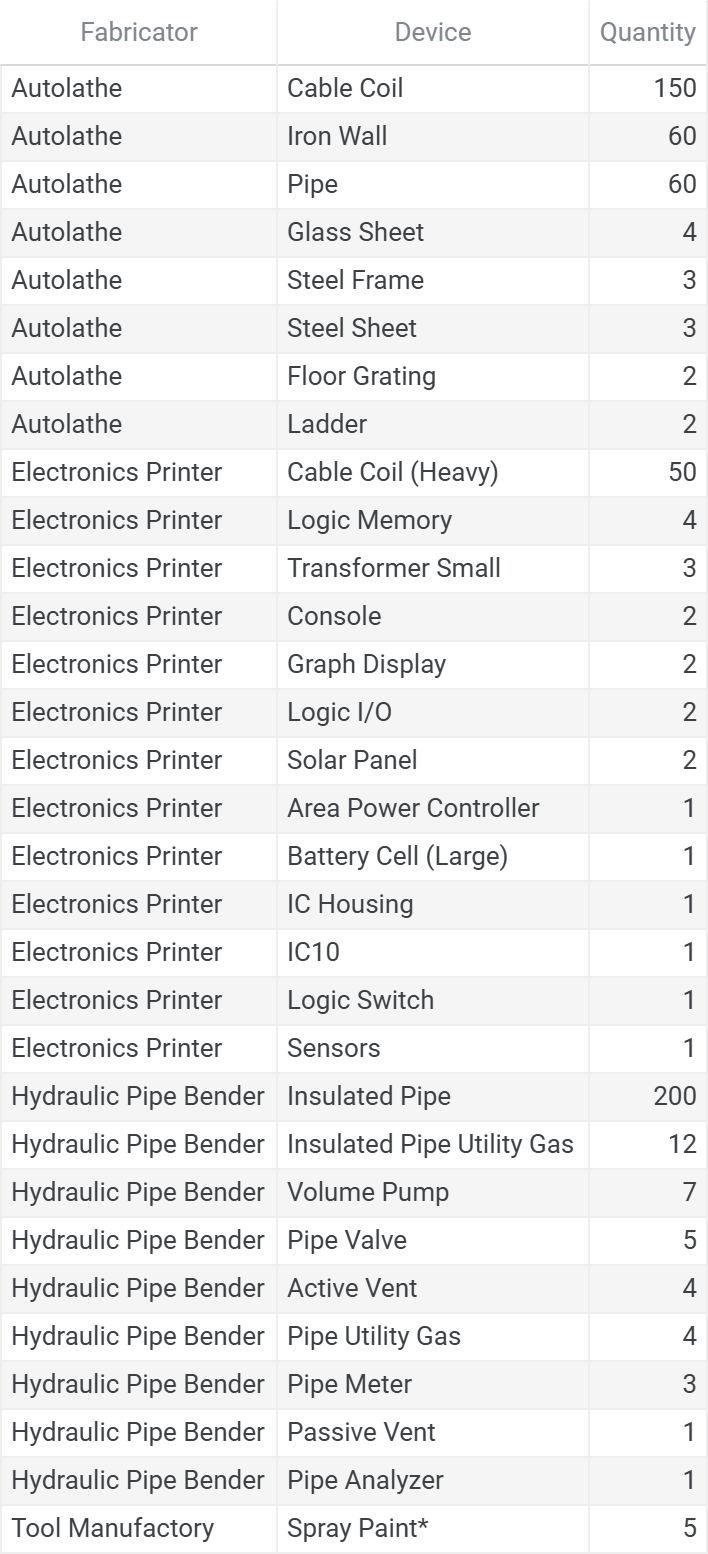
* Spray Paint Colors: 1 Black, 1 White, 1 Gray, 1 Orange, 1 Green
Total Ingots
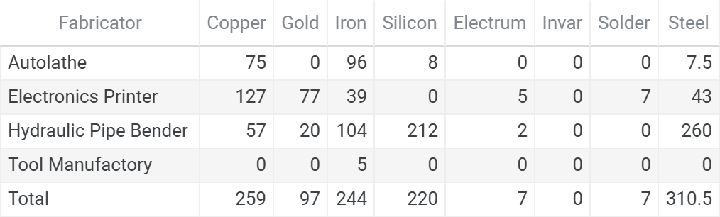
Raw Ores (Stack Rounded Per Fabricator)
This chart format is standardized across the series. See the full legend in Atmospheric Recovery on the Moon, Appendix A11. Bill of Materials.
Ores:

- Coal    -  4 stacks
- Copper  -  7 stacks
- Gold    -  5 stacks
- Iron    - 20 stacks
- Lead    -  1 stack
- Silicon -  6 stacks
- Silver  -  2 stacks

Ingots:

- Copper →
  - Copper: 2/3/2/0
- Gold →
  - Gold: 0/2/1/0
- Iron →
  - Iron: 2/1/3/1
- Silicon →
  - Silicon: 1/0/5/0
- Electrum →
  - Gold:   0/1/1/0
  - Silver: 0/1/1/0
- Solder →
  - Iron: 0/1/0/0
  - Lead: 0/1/0/0
- Steel →
  - Coal: 1/1/2/0
  - Iron: 3/3/6/0
Parallel Construction Tracks
This build consists of three independent construction tracks that can be completed in any order based on priorities and available construction time. While construction can proceed in parallel, the system requires full integration before activation and testing.
Track Overview:
Airlock Enhancement - Enhanced airlock systems to reduce system corrections during cycling operations
Ventilation/Local Gas Line - Sector ventilation and pipe construction
Main Gas Line - High-capacity distribution infrastructure for base-wide atmospheric management
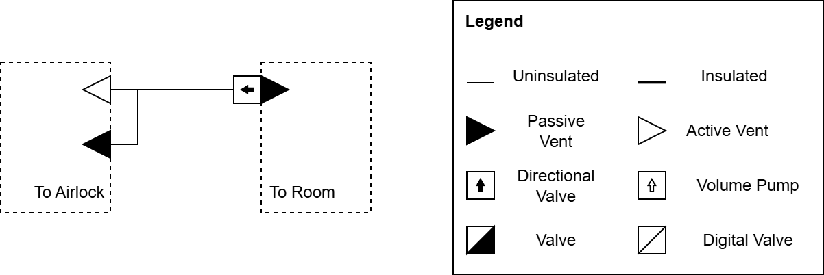
Track 1: Airlock Enhancement
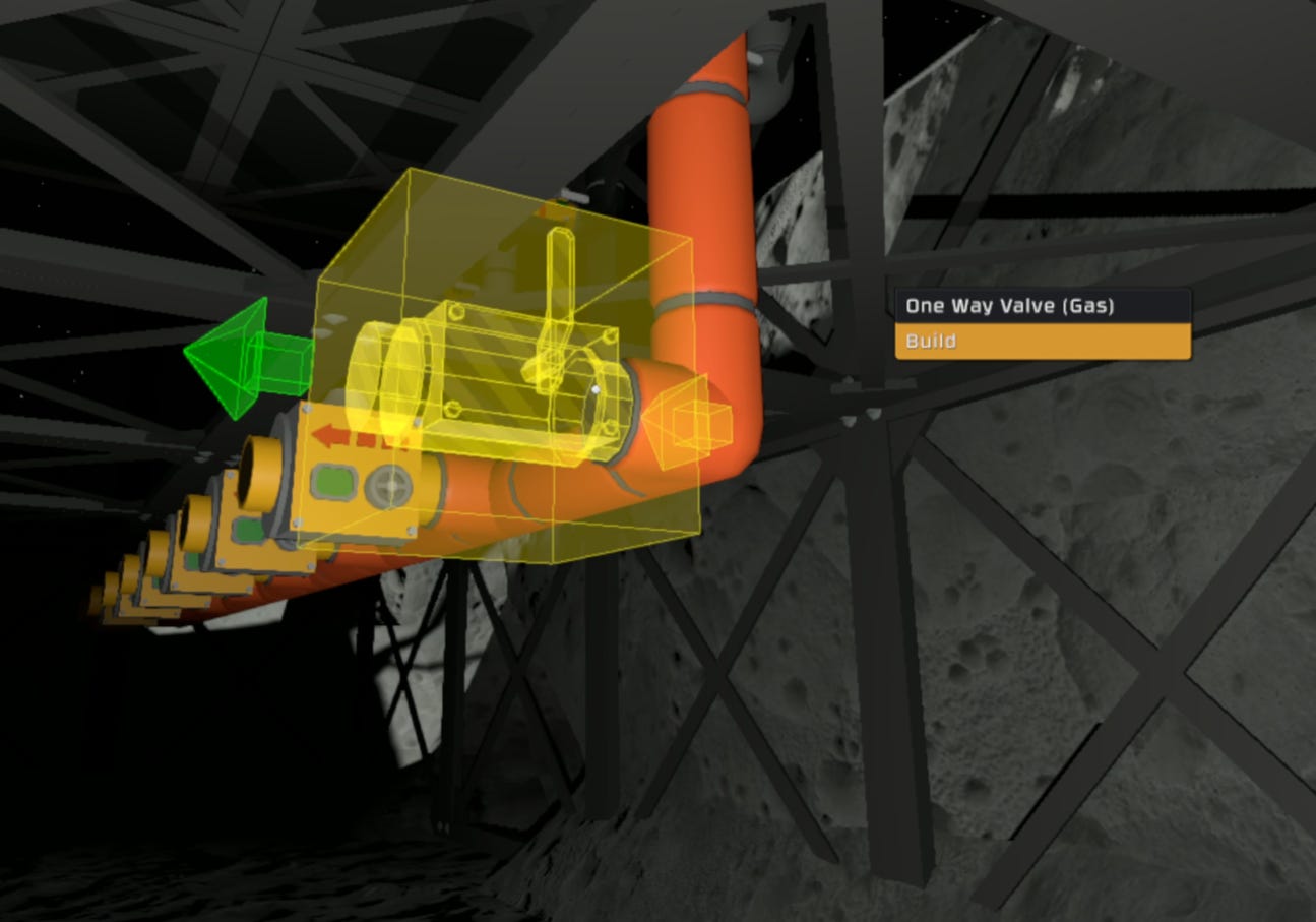
Directional Valve Configuration
Update the airlock pipe system with a directional valve pointing from the room toward the airlock active vent, so that gases remain in the pipe during depressurization, rather than being lost to the room atmosphere.
Pipe Volume Calculation
For pressurization, adequate pipe volume must be provided so that equalization pressure can fill the airlock chamber with 101.325 kPa of gas even if the ambient room pressure is less than that.
Formula:
Where:
Vpipe = Volume of pipe (L)
Pairlock = Airlock target pressure (101.325 kPa)
Proom = Minimum room pressure (kPa)
Vairlock = Volume of airlock chamber (L)
Example: 1 GU Airlock (8000 L) with 97 kPa minimum room pressure:
Constraint: Proom ≤ Pairlock
System Limitation and Override
This enhancement is contingent on room pressure being less than or equal to airlock target pressure. If room pressure continually exceeds airlock target pressure, the pipe will not be able to adequately depressurize.
Override: Attaching a passive vent (valve) provides manual override to dump surplus gases from the pipe into room atmosphere when depressurization cannot complete due to room pressure exceeding airlock pressure.
🚨 Warning: Opening the valve to vacuum will depressurize the entire base through the connected pipe system. Only use for atmospheric dumping to room atmosphere, never to vacuum.
Components Required
1 One-way Valve (Pipe Valve Kit)
1 Inline Tank Gas (2x Pipe Utility Gas Kit)
1 Passive Vent (Valve) (Passive Vent Kit)
Installation Steps
Install the pipe system following build diagram configuration
Place directional valve pointing from room toward airlock active vent.
Install additional volume buffers to provide calculated pipe volume.
Attach passive vent with valve for pipe equalization

Configuration
Directional valve: Set in open position to allow flow from room to airlock.
Override valve: Normally closed, only open for pipe equalization. Do not open into a vacuum.
Validation
Run airlock pressurization and depressurization cycles and ensure none of the room’s ventilation systems activate during normal airlock operation.
Track 2: Ventilation/Local Gas Line
Components Required
4 Active Vents (Carbon Dioxide, Nitrogen, Oxygen, Exhaust)
1 Gas Sensor (Sensors Kit)
3 Pipe Meters
6 In-Line Tank Gas Insulated (Pipe Utility Gas Kit)
7 Volume Pump
3 One-way Valve (Pipe Valve Kit)
1 Pipe Analyzer
4 Spray Paint (Orange, White, Black, Gray)
~80 Insulated Pipe
~50 Cable Coil
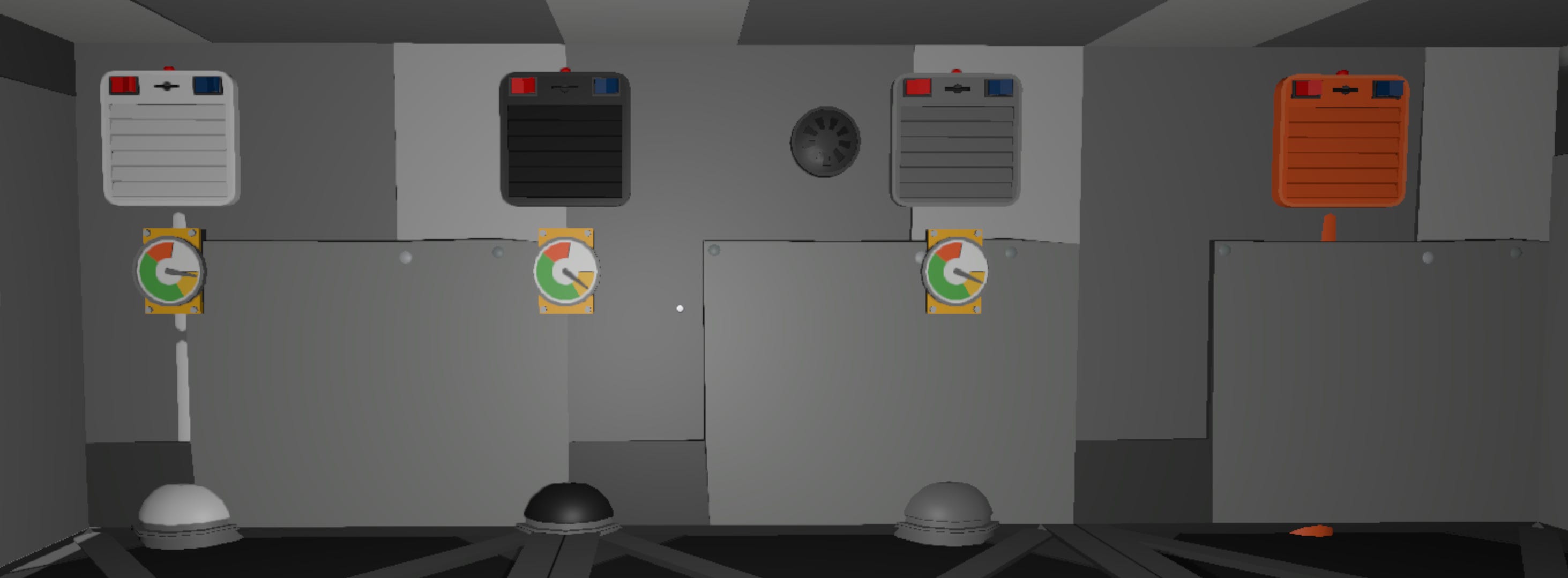
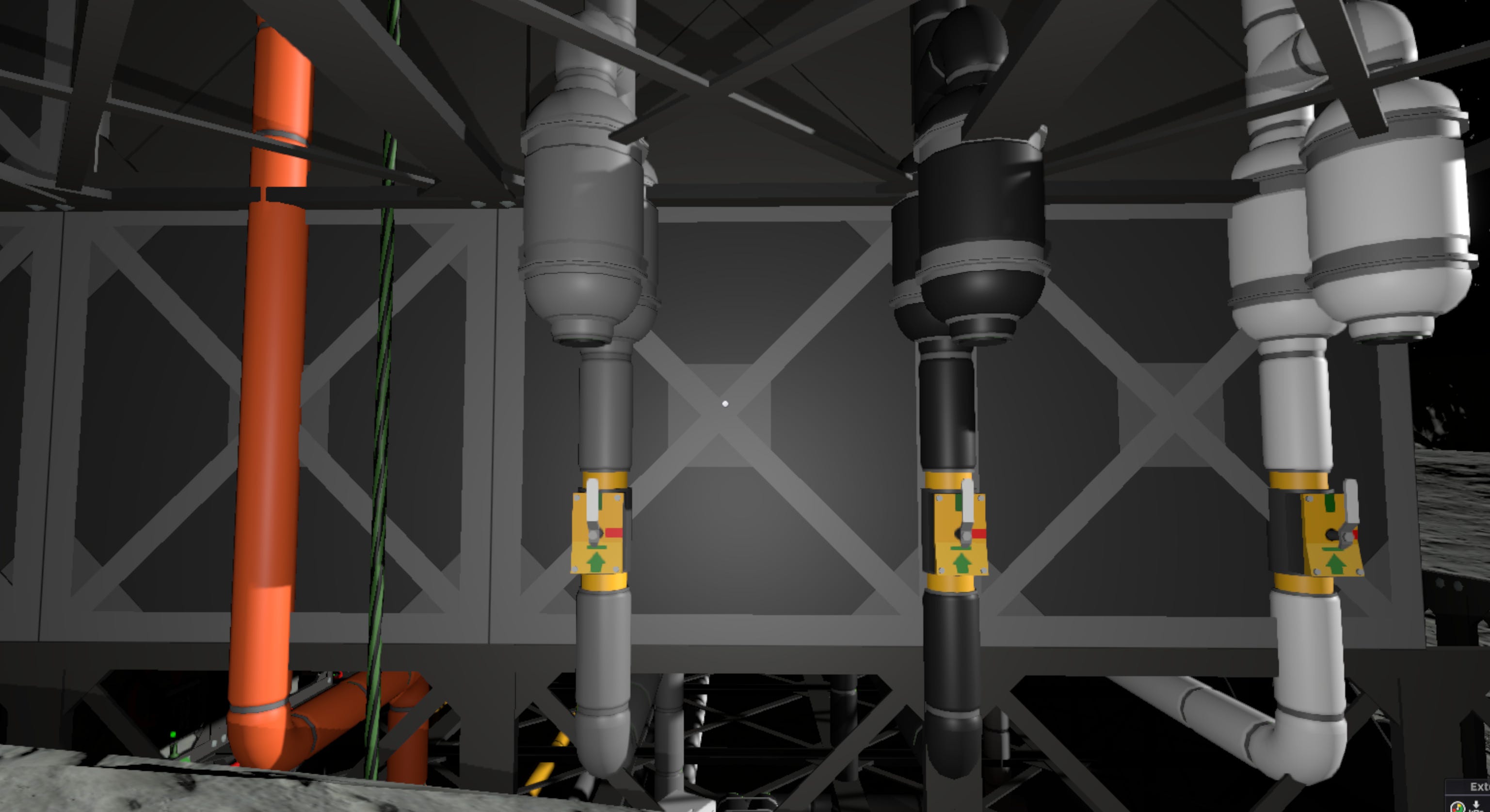
Color Coding System
Paint atmospheric infrastructure based on gas type:
Gray - Carbon Dioxide
Black - Nitrogen
White - Oxygen
Orange - Exhaust
Interior Installation
Install vents and gas sensor inside the base
Attach pipe meters to each gas line
Buffer Volume Configuration
Each outward vent connects to a 550 L pipe to provide adequate buffer volume. This ensures a full pipe can store 33 GU of gas at 100 kPa.
Buffer Volume Formula:
Where:
Proom = Room target pressure (kPa)
S = Room size (GU)
Psafety = Safety limit of main gas line pipe network (kPa)
Directional Valve Installation
At the end of each buffer pipe, attach a directional valve pointing toward the vent.
Exhaust Network Setup
On the exhaust pipe network, install 8 parallel connections that will connect to the main Exhaust Capture Line:
Connect one directional valve, pointing away from the local line.
Connect volume pumps to the remaining 7 connections, also pointing away from the local line.
Connect the pipe analyzer to the local pipe network.
Pipe Routing: Follow the systematic latitudinal/longitudinal pipe layout methodology covered in Track 3: Main Gas Line for organized connection routing.
Zone Expansion Preparation
This local gas line serves as the foundation for future zone expansion. Additional vents can be connected to this network without requiring additional pumps or analyzers.
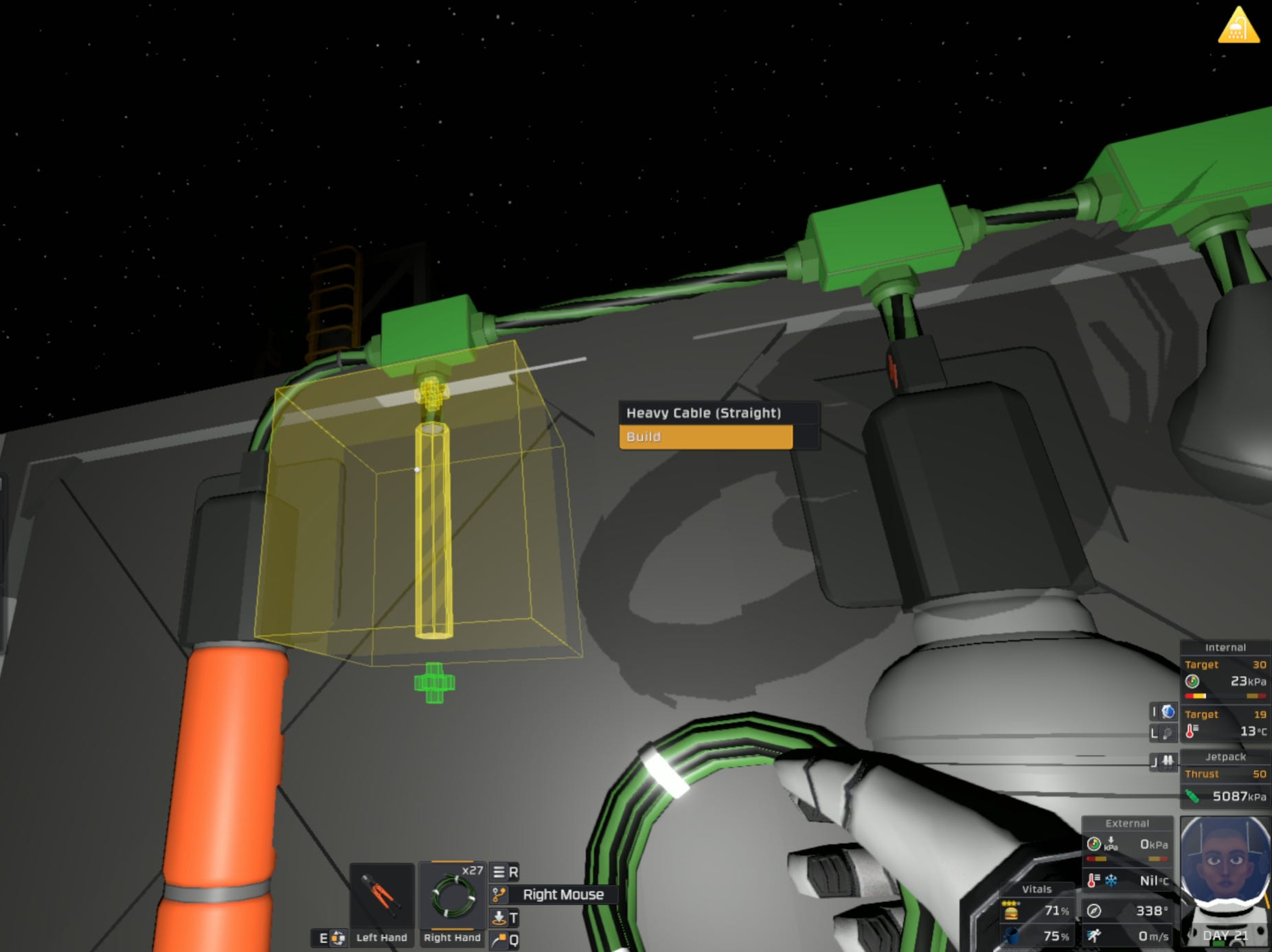
Power Infrastructure
Connect heavy green cables to:
All active vents
Gas sensor(s)
Volume pumps
Pipe analyzer
Configuration
Valve Settings
Open all valves to enable gas flow through the system.
Device Labeling
Use the labeler to assign the following device names:
Outward Vents:
SectorNitrogenSectorCarbonDioxideSectorOxygen
Exhaust Equipment:
Vent, Pipe analyzer, Volume Pumps:
SectorExhaust
Gas Sensor: Sector
Integration Notes
The local gas line integrates with Track 3 to provide sector-level atmospheric control within the broader base infrastructure. Volume pumps and directional valves work together to prevent overpressure while maintaining gas reserves for zone expansion.
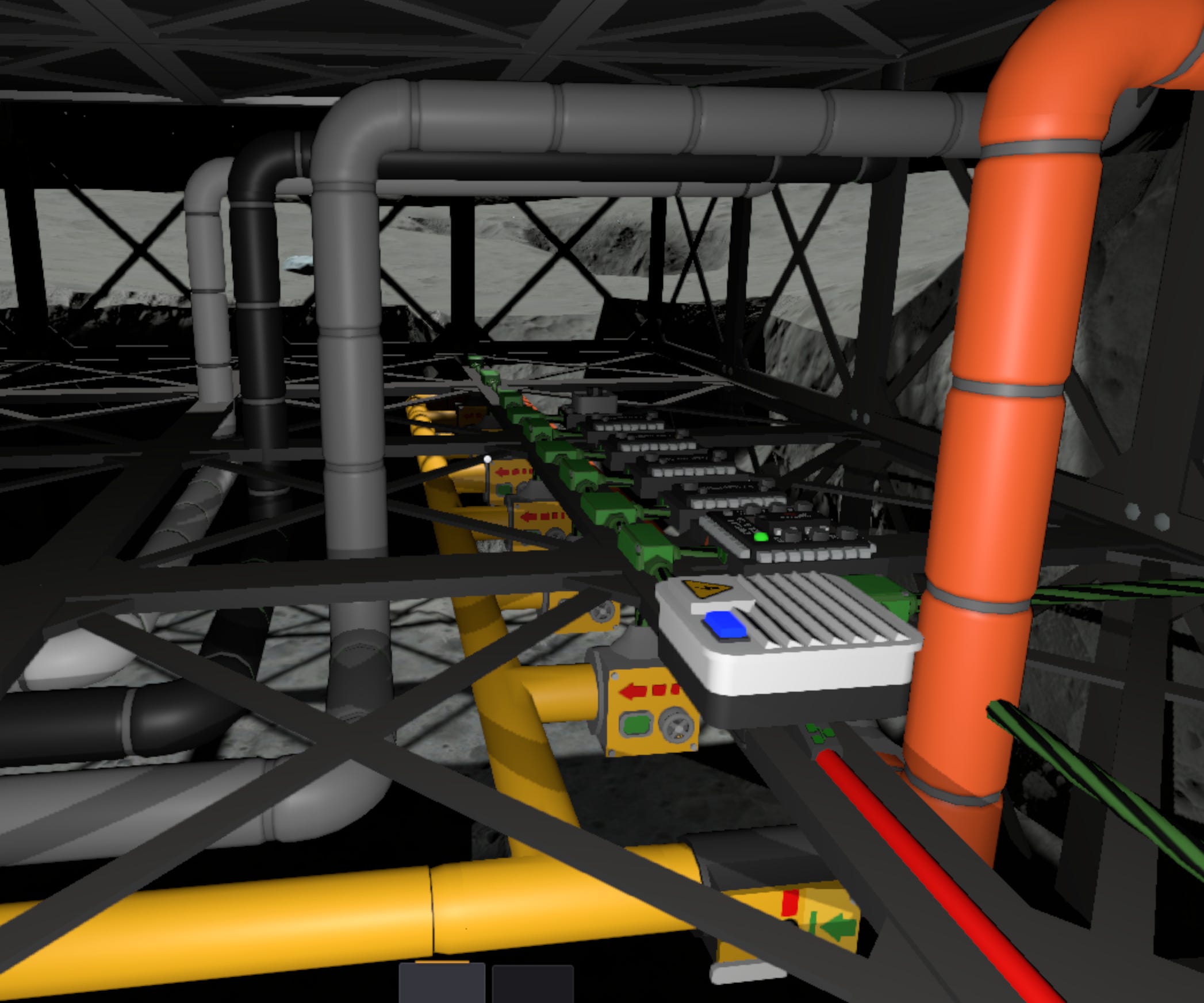
Track 3: Main Gas Line
Pipe Routing Methodology
Pipelines are split over two levels to allow for improved access during maintenance operations. All pipes maintain directional consistency within each level:
Lower level: All pipes run longitudinally (E-W direction) along the ceiling
Upper level: All pipes run latitudinally (N-S direction) along the ceiling
This rule applies to both local gas connections and the main gas line networks.
Wall-Based Routing Logic
North-South walls (vents facing E-W):
Local pipes run longitudinally on lower level
Connect to main gas line running latitudinally on upper level
East-West walls (vents facing N-S):
Local pipes run latitudinally on upper level
Connect to main gas line running longitudinally on lower level
Components Required
~60 Pipe (Main Exhaust Line Only)
~120 Insulated Pipe
Note: Component quantities will vary based on the location of the atmospheric recovery infrastructure.
System Integration Points
Outward Gas Distribution:
Connect outward lines from Processed Gas Lines to main gas line network.
Routes conditioned and filtered gases from atmospheric recovery system to room distribution.
Inward Waste Collection:
Connect inward/exhaust line to the Exhaust Capture Line (ECL)
Collects waste gases from room ventilation systems
Safety Design Philosophy
The system prioritizes local pipe safety over ECL pipe safety, since local pipes are situated along walls with much lower pressure tolerances.
Integration Notes
The main gas line integrates with Track 2 (Ventilation/Local Gas Line) through the perpendicular routing system, ensuring organized pipe management and maintenance access throughout the base infrastructure.
Power Infrastructure
The Zone-0 power network establishes a new life support power domain to manage atmospheric operations:
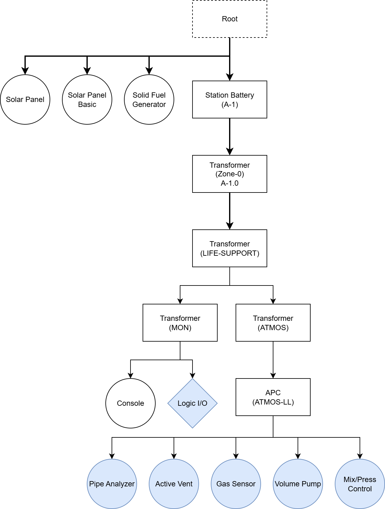
Zone-0 (Medium Transformer, 25 kW)
High wattage line that supplies power to the entire zone
Connects directly to the main power grid
Life Support (Small Transformer, 260 W)
Life support operations including monitoring, atmospherics, and cooling systems.
Fed from Zone-0 transformer
LS-ATMOS (Small Transformer, Green, 130 W)
Supports base atmospheric systems
Normally sized for 66 W but set higher to support atmospheric balancing and expansion
Operator reduces load to normal operating levels once balancing is complete
Fed from Life Support transformer
LS-ATMOS-LL (APC with Large Battery)
Load-leveled network where all atmospheric devices connect
Provides energy storage buffer for peak atmospheric events
Fed from Z01-LS-ATMOS transformer
Connected Devices:
Volume Pumps
Active Vents
Gas Sensors
Pipe Analyzer
Mix/Press Control (IC Housing)
Gas sensor batch reader input
Z01-LS-MON (Small Transformer, 130 W)
Monitoring network supporting computer and graph displays
Fed from Z01-LS transformer
Connected Devices
Gas sensor batch reader power and output
Graph Display Consoles

Logic Initialization and Deployment
Mixture-Pressure Controller
The Mixture-Pressure Controller regulates the pressure and atmospheric mixture of a zone, while maintaining local safe exhaust pipe pressures.
Functional Overview
Activates ventilation systems to maintain correct atmospheric pressures and gas ratios.
Monitors waste pipe pressure to ensure safe levels and activates pumps as needed.
Hardware Interface
d0: Pressure kPa (Memory)d1: Sector Size GU (Dial)d2: Ratio Carbon Dioxide decimal (Memory)d3: Ratio Nitrogen decimal (Memory)d4: Ratio Oxygen decimal (Memory)
Configuration Parameters
- SafetyPressure (Safety Pipe Pressure kPa): 48636
- PressureTolerance (Pipe Pressure Deviation kPa): 3
- MinDisplacement (Minimum Gas Displacement Pressure kPa): 0.3
- Delay (Wait time between atmospheric adjustments tick): 2
- Precision (Decimal precision for value comparisons): 0.001
- Local (label): "Sector"
- LocalCarbonDioxide (label): "SectorCarbonDioxide"
- LocalNitrogen (label): "SectorNitrogen"
- LocalOxygen (label): "SectorOxygen"
- LocalExhaust (label): "SectorExhaust"
Device Mapping
Gas Sensor: Monitors atmospheric conditions within the zone
Outward gas lines (Carbon Dioxide, Nitrogen, Oxygen):
Active Vent: Controls outward ventilation into the zone atmosphere
Inward gas lines (Exhaust):
Active Vent: Controls inward ventilation into the exhaust pipe
Pipe Analyzer: Monitors atmospheric conditions within the local exhaust pipe network.
Volume Pump: Actively removes gases from the local exhaust pipe network.
Procedure
Waste Management
Monitors local exhaust line pressure
Activates pumps when pressure exceeds safety threshold
Prevents pipe burst risk near structurally sensitive areas
Pressure Management
Monitors zone pressure against target
Activates inward vents if pressure exceeds target
Activates outward vents if pressure falls below minimum threshold
Composition Management
Monitors zone atmospheric composition against target ratios
Evacuates excess gases when specific gas concentrations fall below target
Activates appropriate outward vent to exceed target ratio for deficient gas
Uses minimum displacement threshold to prevent unnecessary cycling
Deployment Checklist
Confirm the following before activating any logic-controlled systems. This ensures that the IC program is properly mapped.
Device Labels
Runtime-Required Labels
These labels must match exactly, as they are referenced directly in controller logic:
SectorSectorCarbonDioxideSectorNitrogenSectorOxygenSectorExhaust
Convenience Labels (Recommended)
These device names are not used by logic programs, but make flashing and troubleshooting easier:
Life SupportLS-MONLS-ATMOSMEM-PRESSURE-SETTINGDIAL-SIZE-SETTINGMEM-RATIO-CO2-SETTINGMEM-RATIO-N2-SETTINGMEM-RATIO-O2-SETTINGPressure DisplayGas Ratio DisplayPRESSURE-READERGAS-RATIO-READER
Power System Validation
Power on all network transformers.
Do not turn on the APC; allow the battery to charge to at least 30%.
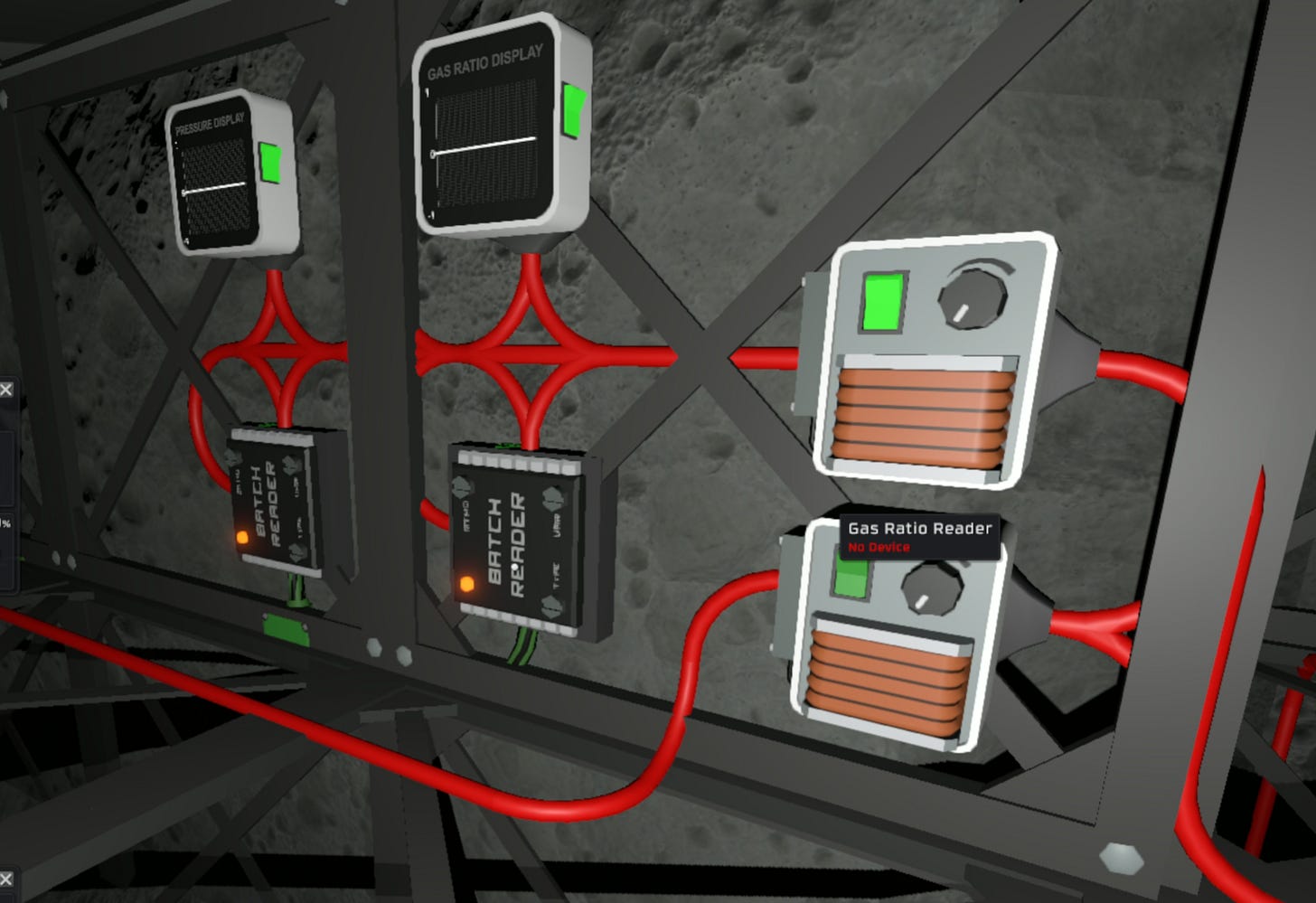
Configure graph display consoles to capture readings from respective Logic Batch Reader chips. This will provide real-time monitoring throughout the activation sequence.
Primary Console (Pressure Monitoring): Configure one console to capture average pressure readings from the gas sensor.
Secondary Console (Gas Composition): Configure the second console to cycle among the three gas ratio readings (CO2, N2, O2).
Record baseline levels before system activation for comparison during operation.
Note: Gas sensors do not require power to operate, ensure that readings are visible from consoles before proceeding with power activation.
With the Mixture-Pressure controller disabled, power the network through the APC and turn on the pipe analyzer. This confirms power distribution is functioning correctly through the load leveling architecture.
Manual Shutdown Protocol: To turn off the system, shut down power through the APC. Do not cut power to the transformer or turn off the controller.
IC10 Chip Installation
Install IC10 program into the logic-capable device
IC10 Pre-Boarding
Power on the computer or laptop used to flash the controller
Confirm the IC Editor motherboard is installed
Load and save IC Program
Final Hold
Do not turn on controller until the full startup sequence has been completed and all systems are confirmed.
System Activation and Handoff
System components, logic device, and power domains are now installed and configured. The system is structurally complete, and control logic is staged for deployment.
However, final logic activation must not proceed until all runtime behaviors have been individually validated and the Readiness Procedure is complete.
Final Preconditions for Runtime Handoff
The system must meet the following conditions before control can be handed off to automated logic:
All IC10 programs are loaded onto the connected computer
Logic files should be saved and flashed with the controller off, allowing for isolated verification of supporting systems.
All devices are labeled and mapped per controller requirements
Includes runtime (e.g.,
SectorExhaust) and convenience labels (e.g.,Pressure Display) for accurate logic targeting and flashing.Consoles properly display gas sensor readings
Displays pressure and composition that will allow for validation and debugging.One-way valves connected to local gas lines are open
This will allow the free flow of gases into and out of the main gas lines.
Proceed to: System Readiness Plan
Next Steps
With advanced atmospheric infrastructure deployed, the base now has the foundation for comprehensive life support capabilities. However, thermal regulation is essential before sustainable food production can begin—without temperature control, greenhouse environments will overheat and kill crops over time.
The load leveling network, integrated control systems and zone level infrastructure enable three key expansions:
Temperature Regulation — Critical prerequisite for sustainable food production. The
Life Supportpower domain can be expanded to support thermal management systems. Future modules will address the thermal calculations and control logic needed to prevent greenhouse overheating and maintain optimal growing conditions.Portables Pressurization and EVA Support — The main gas line network provides distribution capacity for suit recharging stations and portable tank filling. This expansion will cover container safety protocols and pressurization procedures for operational mobility.
Monitoring and Alerting — The console and sensor infrastructure established here supports automated monitoring systems. Future modules will integrate alerting protocols and safety response automation.
Content developed in collaboration with Anthropic's Claude, used for technical documentation structure, engineering analysis, and editorial refinement.