
Vigil Network: Information Architecture and Communication Standards
Alert codes and visual communication for base monitoring
Introduction
The Vigil Network is a distributed alert monitoring infrastructure that collects, prioritizes, and transmits alert codes through visual and audio channels matched to operator distance and decision requirements. The architecture operates on four hierarchical layers: Detection (sensors and threshold evaluation per location), Aggregation (local alert consolidation per room or module), Coordination (facility-wide priority calculation and health monitoring), and Communication (visual beacons for long-range awareness, console displays for detailed status at entry points).
Primary benefits:
Priority-based signal hierarchy Not all alerts carry equal urgency. A fire may demand an immediate response. A warning about approaching capacity limits indicates attention needed before additional expansion can proceed. A maintenance reminder about filter replacement can be scheduled when convenient. The Vigil Network’s priority algorithm ensures severe conditions always propagate to top-level displays, preventing urgent signals from drowning in routine notifications.
Information fidelity gradient Operators at different distances require different information granularity. At long distances, a beacon provides category and severity. At medium range (entrance), a console display provides alert codes, environmental conditions, and PPE requirements. On-site, local diagnostics provide raw telemetry. Information presentation scales with proximity and decision context.
Separation of notification and response The Vigil Network observes and communicates. It does not control fire suppression, atmospheric isolation, or power load shedding. This decoupling prevents monitoring system failures from disabling automated safety responses, and prevents response system failures from eliminating situational awareness.
Architecture Overview
The Vigil Network distributes monitoring functions across four hierarchical layers. Information flows upward from distributed sensors through local aggregation and sector coordination, then returns through communication channels to operators.
A location represents a monitoring boundary defined by network isolation. Locations may monitor interior spaces (habitat modules, processing rooms) or exterior installations (solar arrays, mining sites). All monitoring equipment—sensors, probes, and displays—within a location connect to the same local network.
Detection Layer: Probes
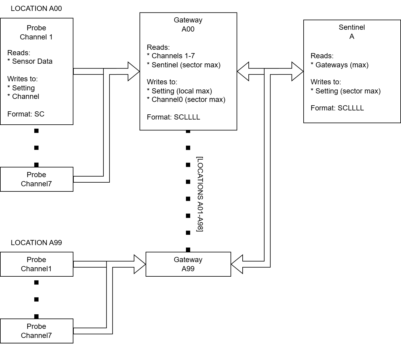
Probes evaluate sensor readings against thresholds and generate alert codes when conditions deviate from normal parameters. Each probe monitors a category of conditions—like environment, power, or hydroponics—and typical locations may deploy up to 7 probes depending on systems that require monitoring.
Aggregation Layer: Gateway
Gateways aggregate alert codes from all probes at a single location. It selects the highest priority alert among local probes and reports it back to the sector-level coordinator. Gateways also relay sector-wide status back to the local network.
Coordination Layer: Sentinel
Sentinel aggregates alert codes from all gateways across the sector. It identifies the facility’s highest-priority alert and broadcasts it to communication systems. Sentinel also monitors gateway health, detecting when locations go offline due to power failures or equipment faults.
Communication Layer: Beacon and Displays
Beacon controllers translate sector alert codes into visual signals—where color indicates alert category and pulse frequency indicates severity. Beacons provide long-range awareness across the facility. Display controllers present detailed information at location entrances: sector-wide status, local status, and environmental conditions. Displays enable operators to assess conditions before entering compartments.
Information Architecture
Alert Code Format
Alert code is encoded as a compact numeric code that is optimized for transmission, storage, and priority comparison. Probes emit a two-digit SC format to show severity and strategy.
Structure
Where:
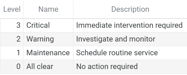
S (Severity): Urgency level, range 0-3
C (Category): System type, range 1-7
Examples:
Code 37: Severity 3 (Critical), Category 7 (Environment)
Code 26: Severity 2 (Warning), Category 6 (Power)
Code 15: Severity 1 (Maintenance), Category 5 (Atmospherics)
Code 07: Severity 0 (All clear), Category 7 (Environment)
Critical alerts (31-37) always take precedence over warnings (21-27), which take precedence over maintenance (11-17). When multiple alerts share the same severity, category determines priority—a critical environment issue (37) outranks a critical power issue (36).
This encoding eliminates the need for lookup tables or complex comparison logic. Gateways and Sentinels calculate priority by simple numeric comparison of SC codes.
Severities
Categories
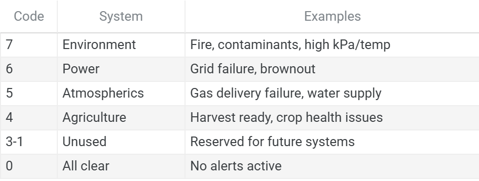
Categories are ordered to reflect system interdependency and cascading failure potential.
Location Encoding
Gateways transform probe-level alert codes from SC format (2-digits) to SC-LLLL format (6 digits) by appending location identification. This transformation preserves severity and category information while adding geographic context.
Transformation
Where:
SC: 2-digit alert code from probe
LLLL: 4-digit location identifier (Sector + Room)
Examples:
Code 37 at Location 0102 → 370102
Code 26 at Location 0101 → 260101
Code 17 at Location 0105 → 170105
Location Format
The 4-digit location identifier encodes both sector and room:
SS: Sector (01-99)
RR: Room (01-99)
By convention, sectors are often labeled alphabetically (A=01, B=02, C=03, etc.) for human readability, while the numeric encoding is used in alert codes.
Examples:
Location 0102: Sector A, Room 02 (e.g. Atmospheric Recovery)
Location 0101: Sector A, Room 01 (e.g. Main Habitat)
Location 0205: Sector B, Room 05 (e.g. Solar Array)
Priority Preservation
The SC-LLLL encoding preserves the priority relationship established by the SC format. When comparing 6-digit codes, the first two digits (severity and category) dominate the comparison.
Location does not affect priority. Multiple locations may report identical SC codes (e.g., 370102 and 370105 both reporting Critical Environment). Sentinel’s maximum calculation will select one based on numerical comparison, but this is incidental—both represent equally urgent conditions. Operators must check local status at each location to assess the full scope of simultaneous failures.
Haven Monitoring
Haven is a controller that monitors atmospheric conditions to determine PPE requirements for safe compartment entry. Unlike probes, which detect threshold violations and generate alerts, Haven provides continuous environmental status independent of alert conditions. This separation ensures operators always know PPE requirements, whether or not an alert is active.
Environment Codes
Haven outputs a single-digit environment code indicating required PPE level:
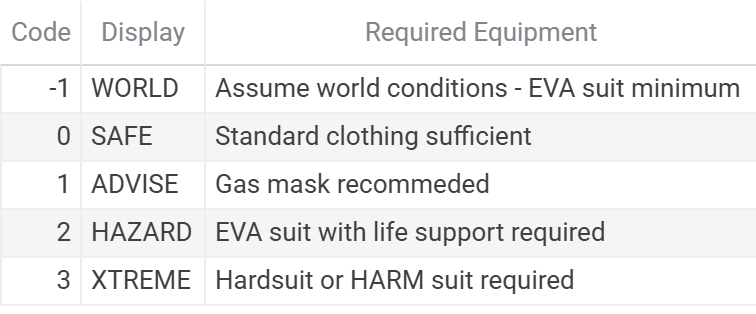
Code -1 (WORLD): Indicates either Haven controller initialization sequence or absence of atmospheric monitoring. Display shows WORLD to indicate environmental data unavailable.
Code 0 (SAFE): Breathable atmosphere within comfortable temperature range, no contamination. Standard clothing sufficient.
Code 1 (ADVISE): Minor atmospheric issues—like contamination where gas mask provides additional safety margin. Entry permitted but respiratory protection recommended.
Code 2 (HAZARD): Significant environmental hazards—vacuum, extreme temperature, high contamination levels. EVA suit with life support required for entry.
Code 3 (XTREME): Extreme conditions beyond standard EVA suit rating—extreme thermal load, crushing pressures. Hardsuit or HARM required.
Visual Communication
The Vigil Network provides different information density based on operator distance from an incident. This graduated approach matches information detail to decision requirements at each stage of response.
Long Range: Beacon Operators at a distance require situational awareness: “Is there an issue? What type? How urgent?” The beacon provides category (color) and severity (pulse rate), visible across the map. This enables initial response decisions—whether to return to base and what equipment to prepare.
Close Range: Display At compartment entrances, console displays provide detailed information: specific alert codes (sector-wide and local), environmental status, and PPE requirements. Operators assess whether entry is safe, what equipment is required, and what conditions to expect inside.
On-Site: Diagnostics Inside the compartment, operators can directly inspect controller outputs, sensor values, threshold settings, and logic states. This diagnostic-level information supports troubleshooting and root cause analysis.
This gradient serves operator workflow: broad awareness at distance, specific details at decision points, diagnostic data during intervention.
Beacon Encoding
Beacons use color and pulse frequency to communicate alert category and severity. This encoding is standardized to ensure consistent interpretation across facilities.
Color to Category Mapping
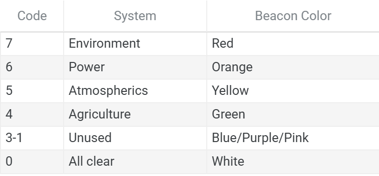
Colors are ordered warm-to-cool, decreasing in visual intensity as category priority decreases. This gradient provides intuitive urgency perception: warm colors (red, orange, yellow) indicate critical life support systems requiring faster response, while cool colors (blue, purple, pink) indicate lower priority systems. White signals all-clear status.
Pulse Rate to Severity Mapping
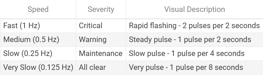
Faster pulse rates indicate higher urgency. Pulsing operation (50% duty cycle across all severity levels) reduces beacon power consumption to 150 W compared to 300 W for continuous operation, while maintaining visible confirmation that the monitoring system is active.
State Transition Behavior
Beacon state changes occur during the OFF phase of the pulse cycle. This prevents intermediate flicker or color mixing during transitions, ensuring operators always see a clear, unambiguous signal. A beacon transitioning from Warning Power (0.5 Hz orange) to Critical Environment (1 Hz red) will complete its current OFF phase before switching to the new color and pulse rate.
Display Information
Console displays at location entrances present information through multiple frames. Each frame serves a specific operator decision. Frames are displayed sequentially, with some frames appearing conditionally based on current status.
Frame 1: Sector Alert
Content: Sector-wide highest priority alert (SC-LLLL format)
Source: Gateway Channel 0 (reading Sentinel status)
Display: Always
Frame 2: Local Alert
Content: This location’s highest priority alert (SC format)
Source: Max of all probes
Display: Only shown when local alert exists (>10), otherwise skipped
Frame 3: Environment Status
Content: PPE requirement code (WORLD/SAFE/ADVISE/HAZARD/XTREME)
Source: Haven controller Setting register
Display: Always
Frame 4: Fire Status
Content: FIRE, if detected
Source: Direct sensor read
Display: Only when fire detected and gas sensor installed, otherwise skipped
Frame 5: Nitrous Oxide
Content: Nitrous Oxide concentration percentage (green text)
Source: Direct sensor read
Display: Only when gas sensor installed, otherwise skipped
Frame 6: Pollutant
Content: Pollutant concentration percentage (yellow text)
Source: Direct sensor read
Display: Only when gas sensor installed, otherwise skipped
Frame 7: Volatiles
Content: Volatiles concentration percentage (red text)
Source: Direct sensor read
Display: Only when gas sensor installed, otherwise skipped
Network Architecture
Single Network Configuration
The single network configuration organizes monitoring infrastructure in two tiers: sector-level coordination and location-level monitoring. All equipment shares power from a common sector transformer.
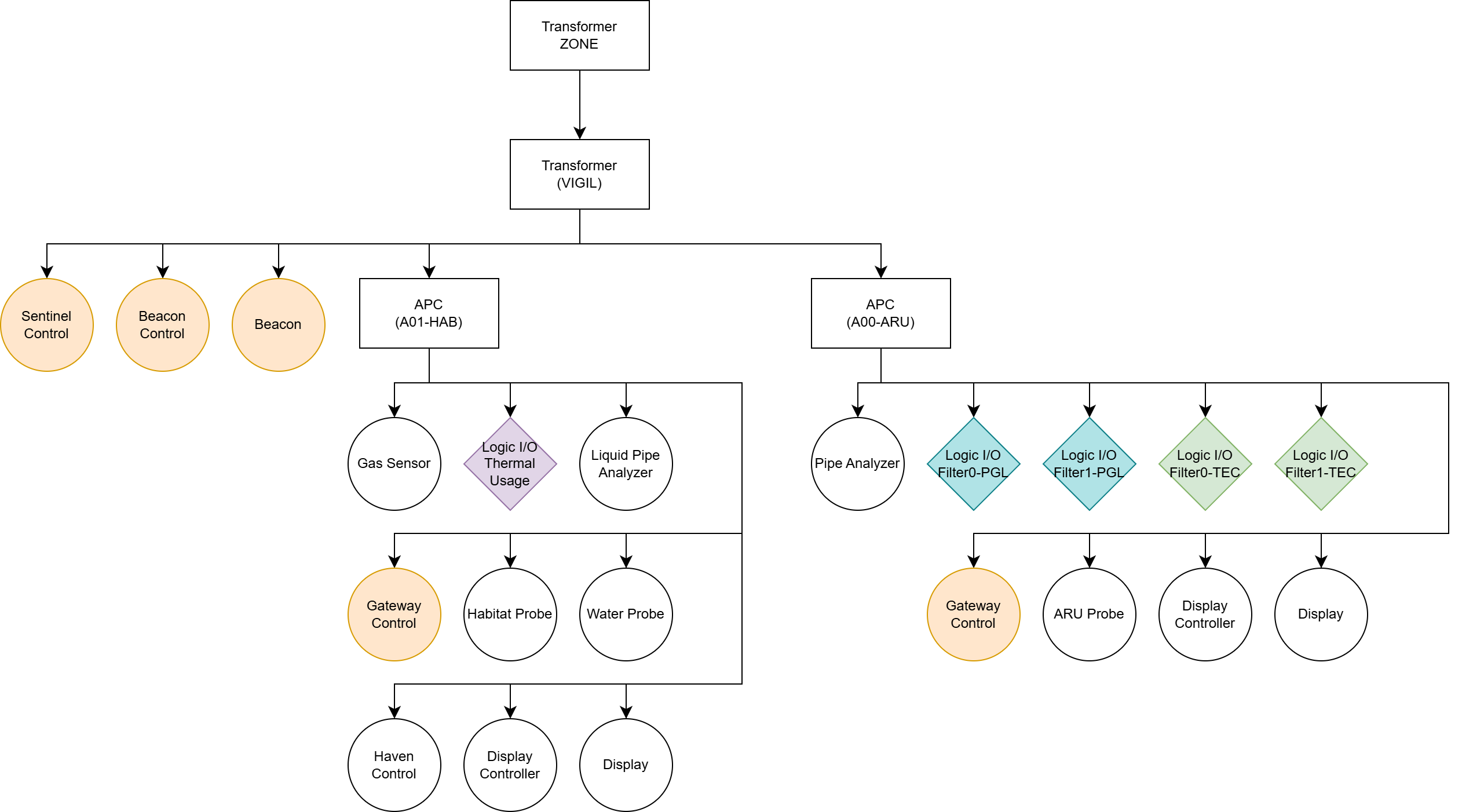
Network Tiers
Sector-level (Vigil transformer): Sentinel, Beacon Controller, Beacon, and Gateway data ports share this network. Only the Sentinel performs batch operations at this tier.
Location-level (APCs): Each location operates an isolated network for local monitoring equipment—probes, Haven, displays, and sensors. Channels 0-7 are local to each location.
Gateway Bridging
Gateways connect the two tiers. It draws power from the local APC, but its data network connects to the Vigil transformer. This enables:
Reading local probe channels (Channels 1-7)
Writing Setting register (for Sentinel batch read)
Reading Sentinel status (sector-wide alert)
Writing to local Channel 0 (distributing sector status to displays)
Sentinel Coordination
The Sentinel aggregates sector status and monitors system health. It batch-reads all Gateway Setting registers, calculates maximum priority, and counts responding gateways. If any Gateway fails to respond (power loss, equipment fault), the Sentinel issues a HealthcheckOffline alert (360000), warning operators of degraded monitoring coverage.
Other devices read from Sentinel rather than reimplement the same calculation. This minimizes code duplication and supports the addition of new health checks as needed.
Scalability
Supports around 8-15 locations per sector under a 5000 W transformer. Typical power consumption per location 250-600 W. For larger facilities or enhanced failure isolation, the split-network configuration provides an alternative architecture.
Split-Network Configuration (Advanced)
The split-network configuration separates sector coordination infrastructure (Sentinel, Beacon) from location monitoring equipment onto independent subnetworks. This architecture provides enhanced failure isolation and supports integration with hierarchical power distribution described in Microgrid Architecture for Resilient Power Systems
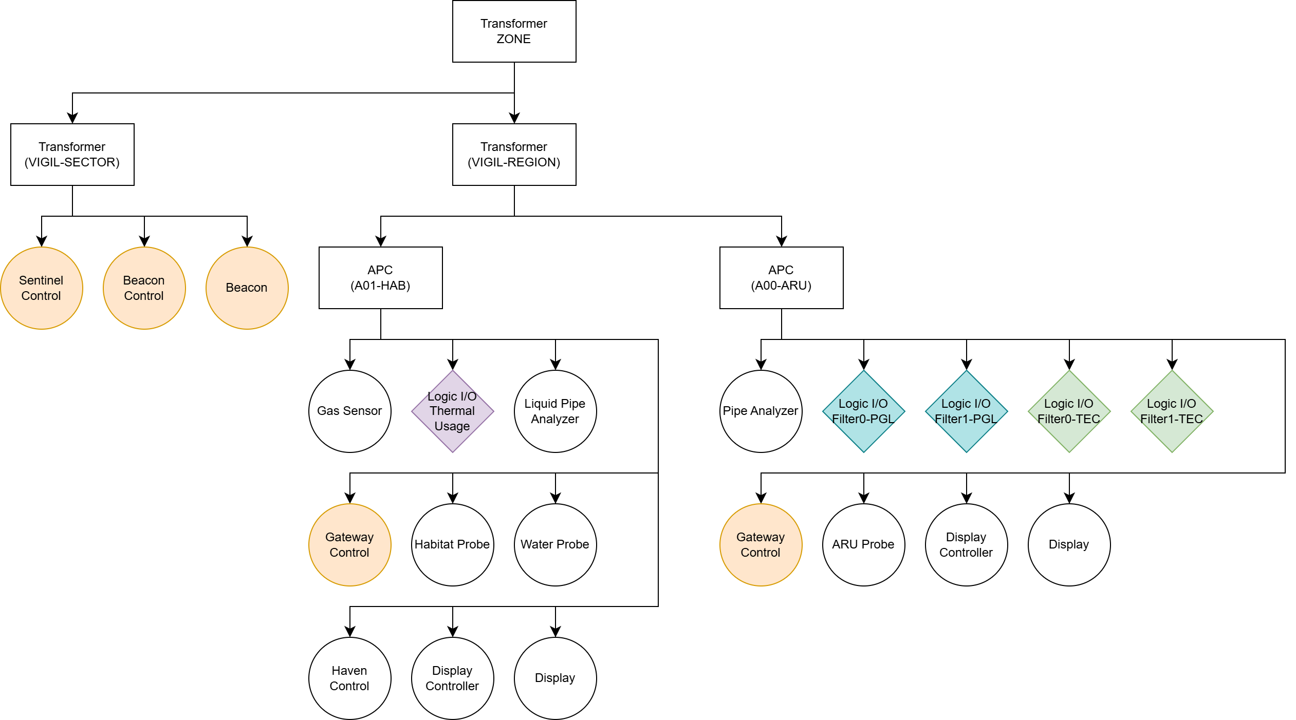
Key Benefits:
Failure isolation: Location power failures do not affect sector coordination
N+1 redundancy: Sentinel connects to multiple regions within the sector, tolerating single-region failures
Power prioritization: Coordination systems receive high-priority zone allocation while location monitoring operates on lower-priority zones
Scalability: Supports larger facility deployments beyond single-transformer limits
When to consider split-network architecture:
Facilities requiring 15+ locations per sector or multiple regions that require coordinated monitoring
Deployments where monitoring coverage must survive regional power failures
Integration with priority-based load management where Sentinel warrants N+1 redundancy while location probes accept regional downtime
Links to Implementation
For operators ready to implement the Vigil Network within their own base, the following implementation guide walks through the full construction process—complete with layout considerations, materials, and programmable logic:
Safety I: Alert Monitoring - Implementation guide covering IC10 code, wiring diagrams, component specifications, and deployment procedures for distributed alert monitoring across facility locations.
Reference Materials
Vigil Network Reference Guide - Operator quick reference and response procedures. Alert code tables, beacon interpretation, and display reading workflows.
Appendix
A1. Glossary
This glossary defines terminology specific to the Vigil Network architecture documented in this article. For broader Stationeering Systems terminology, refer to the Terminology Reference.
Alert Code — 2-digit (SC) or 6-digit (SC-LLLL) numeric code representing severity, category, and location
Category — Type of system being monitored (Environment, Power, Atmospherics, Agriculture), encoded 1-7, maps 1:1 with cable channels
Channel — Cable bus address (0-7) for controller communication within a location
Environment Code — PPE requirement (-1 to 3) for safe entry location: WORLD, SAFE, ADVISE, HAZARD, XTREME
Gateway — Controller that aggregates Probe alerts for a location and coordinates with Sentinel
Haven — Controller that monitors environment conditions (temperature, pressure, contaminants) and calculates PPE requirements
HealthcheckOffline — Special alert (360000) indicating power failure affecting monitoring coverage
Location — A monitoring boundary defined by network isolation. Locations may be interior spaces (habitat modules, processing rooms) or exterior installations (solar arrays, mining sites). Location identifiers use 4-digit format SSRR (Sector + Room), e.g., Location 0102 = Sector 01, Room 02.
Probe — Controller monitoring specific conditions, reports to one category only (1-7 probes per location)
SC Format — 2-digit alert code (Severity × 10 + Category)
SC-LLLL Format — 6-digit alert code (SC × 10000 + Location), created by Gateway
Sentinel — Sector-level controller that coordinates Gateway outputs and performs health checks
Severity — Urgency level (0-3): All Clear, Maintenance, Warning, Critical
Vigil Network — Complete notification system (Probes, Gateway, Sentinel, Beacon/Displays)
A2. References
Stationeers Wiki. Console https://stationeers-wiki.com/Console
Stationeers Wiki. Beacon https://stationeers-wiki.com/Beacon
Stationeers Wiki. IC10 https://stationeers-wiki.com/IC10#Network_Referencing_.2F_Channels
Content developed in collaboration with Anthropic’s Claude, used for technical documentation structure, engineering analysis, and editorial refinement.