
Life Support III: Radiative Cooling
Building and Commissioning a Radiative Cooling System for Small-Scale Operations
Note for independent readers: This document assumes prior familiarity with the architectural principles and subsystems outlined in the broader Stationeering Systems framework. Readers seeking system-level rationale or integration context are advised to consult the foundational document Radiative Cooling Strategies for Habitat Sustainability for comprehensive design overview.
Prerequisites
Collect approximately 13.011 moles of carbon dioxide in a pressurized canister
Understand how PID controllers work
Objectives
Keep base temperatures within manageable thresholds
Constraints
Maintain base atmospheric temperatures between 293 K-303 K (20-30 °C)
Must be able to mitigate the effects of solar heating emanating from windows and pipe infrastructure
This includes transient solar storm events that can increase solar thermal output by 400%
Must provide a simple metric used to evaluate thermal load and to measure cooling performance
Implementation Context
The greenhouse will produce the base’s highest thermal loads through solar heating. During lunar day cycles, windows admit approximately 77 W per panel of continuous thermal energy—heat that accumulates regardless of equipment state or power availability. Thus, the greenhouse requires dedicated cooling infrastructure that operates independently of other base systems.
This implementation establishes the base’s first radiative cooling unit as a Dedicated Thermal System (DTS) integrated into the greenhouse power hierarchy. The DTS mounts directly within the greenhouse where solar heating is most concentrated, positioning convection radiators neat the primary heat source for maximum heat absorption efficiency.
The system is initialized in thermal tracking mode to characterize both the greenhouse and base’s aggregate heat load. Since the greenhouse shares atmosphere with adjacent compartments, the cooling system removes heat from the entire connected volume, not just the greenhouse itself. Pump speed telemetry quantifies total heat dissipation in time: as pump speeds drop toward zero, the system approaches capacity limits, indicating when additional cooling units are required or when transition to thermal pulse mode (75 W average vs 875 W continuous) becomes appropriate for steady state operations.
This characterization phase answers critical infrastructure questions: What is the base’s actual thermal load during different solar conditions? How much cooling capacity is consumed by windows versus equipment versus biological activity? When does solar storm duration exceed the system’s thermal buffering capacity? These measurements inform all future cooling deployments and determine when sector-wide thermal management (STS) becomes necessary as the base expands.
Materials and Components
Fabricated Components
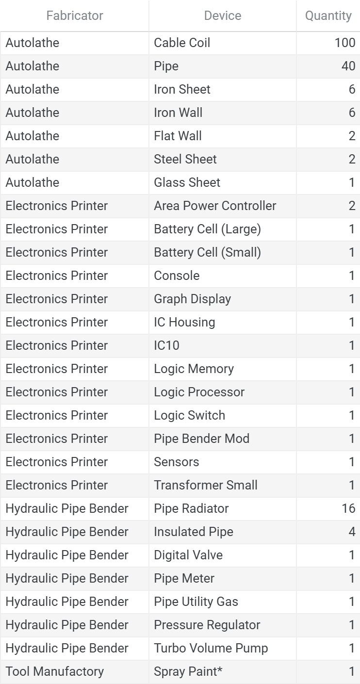
* Spray Paint Colors: 1 Purple
Total Ingots
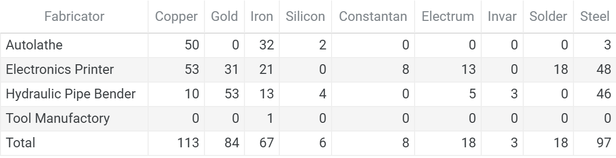
Raw Ores (Stack Rounded Per Fabricator)
This chart format is standardized across the series. See the full legend in Atmospheric Recovery on the Moon, Appendix A11. Bill of Materials.
Ores:

- Coal    -  3 stacks
- Copper  -  5 stacks
- Gold    -  5 stacks
- Iron    - 15 stacks
- Lead    -  1 stacks
- Nickel  -  2 stacks
- Silicon -  2 stacks
- Silver  -  2 stacks

Ingots:
- Copper →
  - Copper: 1/2/1/0
- Gold →
  - Gold: 0/1/2/0
- Iron →
  - Iron: 1/1/1/1
- Silicon →
  - Silicon: 1/0/1/0
- Constantan →
  - Copper:   0/1/0/0
  - Nickel: 0/1/0/0
- Electrum →
  - Gold:   0/1/1/0
  - Silver: 0/1/1/0
- Invar →
  - Iron:   0/0/1/0
  - Nickel: 0/0/1/0
- Solder →
  - Iron: 0/1/0/0
  - Lead: 0/1/0/0
- Steel →
  - Coal: 1/1/1/0
  - Iron: 3/3/3/0
Floorplan
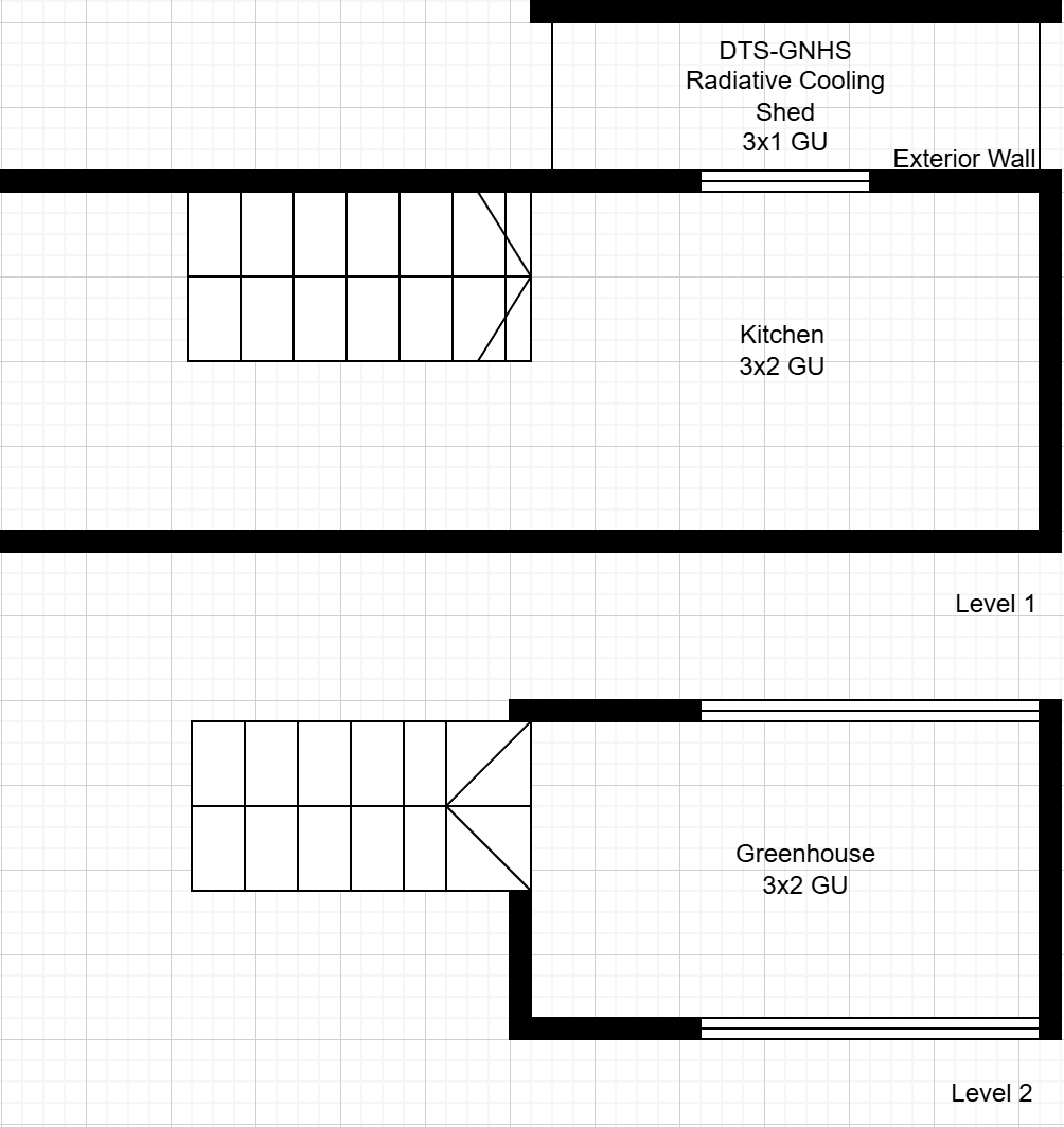
The greenhouse occupies a 3x2 GU space on Level 2, directly above the kitchen. Both compartments share atmosphere through an open stairwell, meaning the cooling system removes heat from the combined volume rather than the greenhouse alone. The DTS-GNHS Radiative Cooling Shed serves as a staging area for the cooling system’s exterior components.
Radiative Cooling Shed
The radiation segment requires vacuum exposure to reject heat into space, but direct solar exposure during lunar day cycles heats the radiator pipes and reduces cooling effectiveness. A dedicated cooling shed addresses this conflict by providing vacuum access while shielding radiators from solar radiation.
Shed Purpose and Design:
Unpressurized structure attached to greenhouse exterior wall
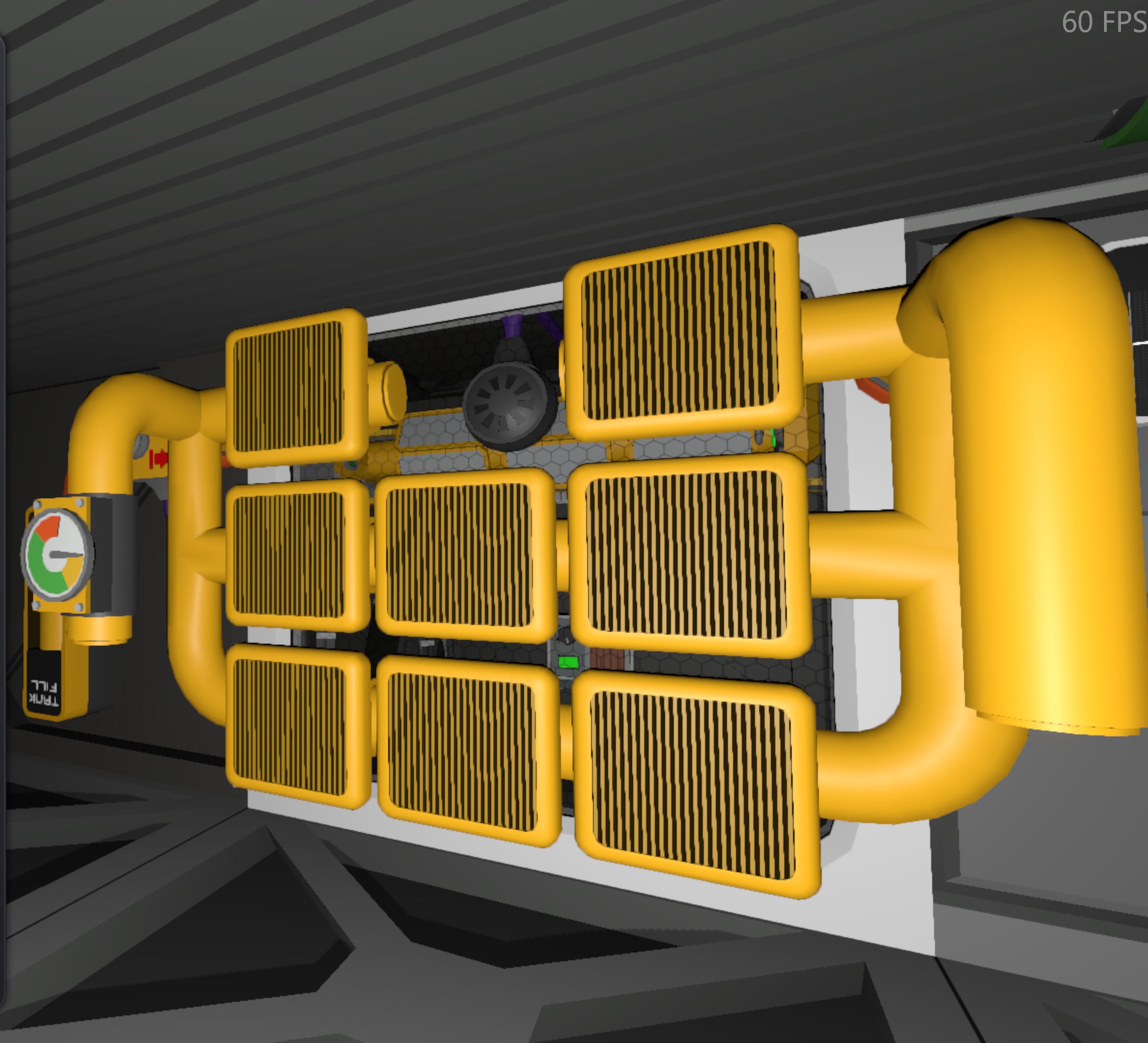
Houses the 100L radiation pipe segment and 8 pipe radiators
Blocks direct solar heating of radiator surfaces during day cycles
Maintains vacuum exposure for radiative heat rejection
Placement Considerations:
The shed requires sufficient depth for accessibility and to accommodate radiator mounting without surface contact (radiators must suspend in open space to maintain full radiative efficiency) and clearance for pipe routing between the radiation and convection segment through the wall.
Ensure that the shared wall between the convection and radiation segments are enclosed from both sides so that maintenance can be performed from both interior and exterior locations.
Pipe Network
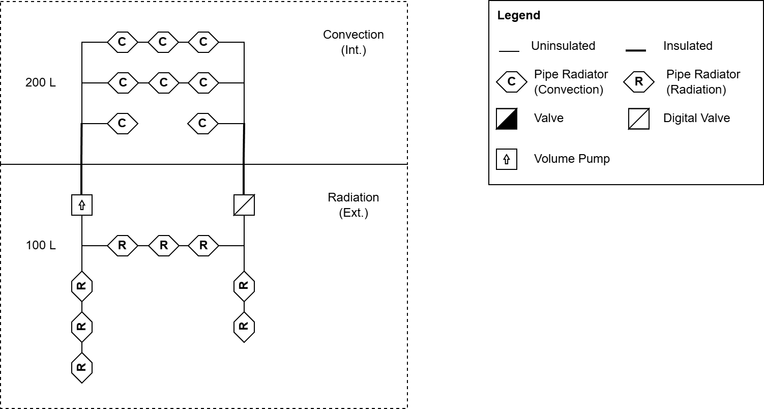
Radiation Segment:
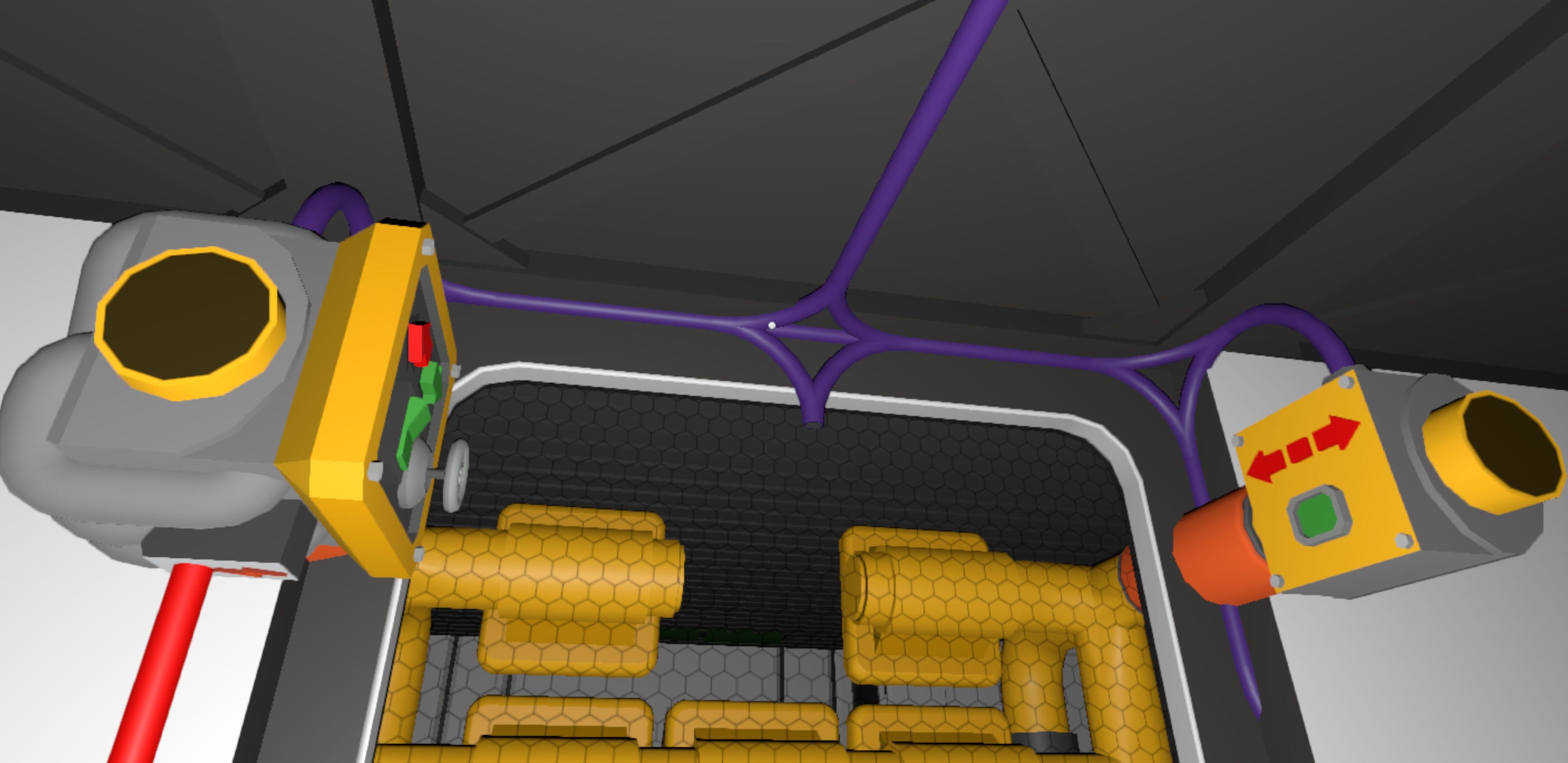
Place two insulated pipes that cross through either side of the window and attach the digital valve and turbo pump such that the displays are facing toward each other and that the power connections are pointing toward the ceiling.
The power connection for the turbo pump should be facing downward
The green arrow of the turbo pump should be pointing toward the base interior
Attach 100 L of pipe and connect 8 radiators.
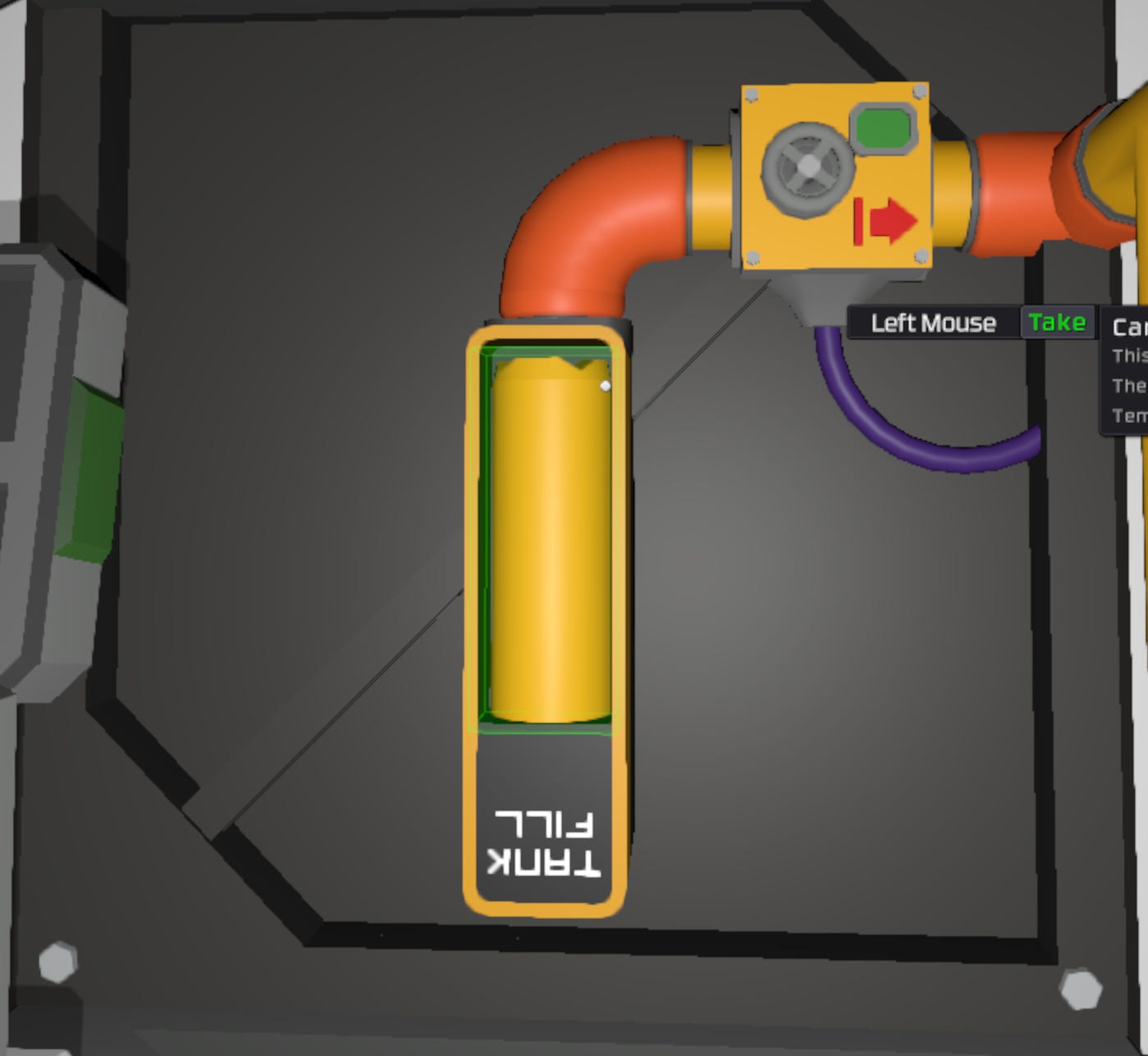
Gas Charging Line:
The gas charging line is infrastructure used inject carbon dioxide gas into the cooling system from a portable canister source. This piece of temporary infrastructure is only needed for initial commissioning and decommissioning of the unit and can be optionally disassembled once charging is complete.
Add a junction to one of the existing insulated pipe segments and attach a pressure regulator, followed by a 10 L pipe segment and a gas canister storage.
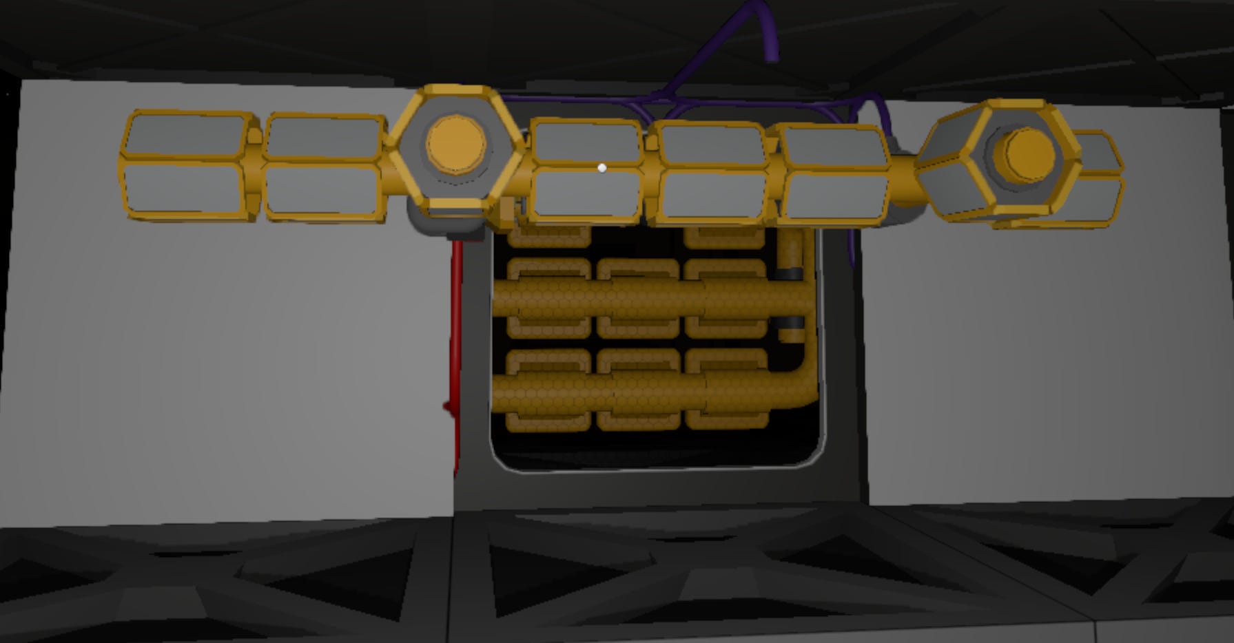
Convection Segment:
Attach the piping required create a 200 L convective pipe volume with 8 convection pipe radiators, along with a pipe meter to monitor the pressure and temperature of the pipe.
Power Infrastructure
The DTS deploys as a child network of the greenhouse power hierarchy, connecting downstream of the greenhouse transformer. This creates an explicit dependency: when the greenhouse loses power, the cooling system automatically shuts down with it.
Although the system serves the entire base’s thermal load, the cooling system integrates into greenhouse power, rather than zone power. This placement reflects the greenhouse as the primary heat source through solar heating and anticipated heat loads.
Installation
GNHS-THERM (925 W)
Increase Greenhouse transformer power to support the added energy load.
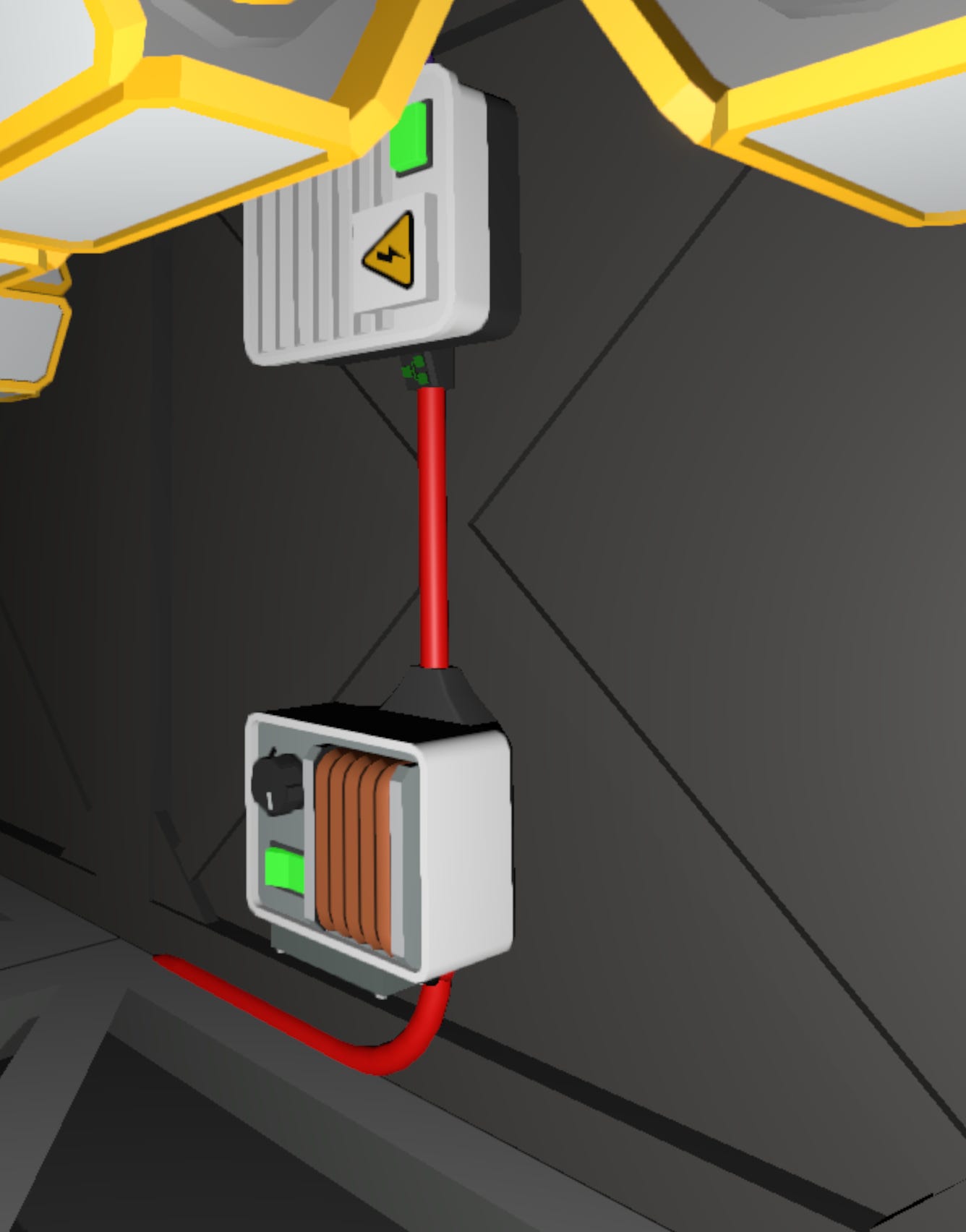
Connect cable from Greenhouse transformer output to GNHS-THERM transformer input.
Connect cable from the GNHS-THERM transformer output to the THERM-LL area power controller input
Insert a large battery into the GNHS-THERM area power controller
Turn on network devices and ensure active power flow to the THERM-LL APC junction

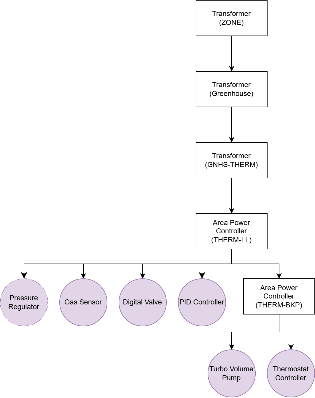
Active power flow from the GNHS-THERM transformer to the THERM-LL area power controller. THERM-LL (Battery Cell Large)
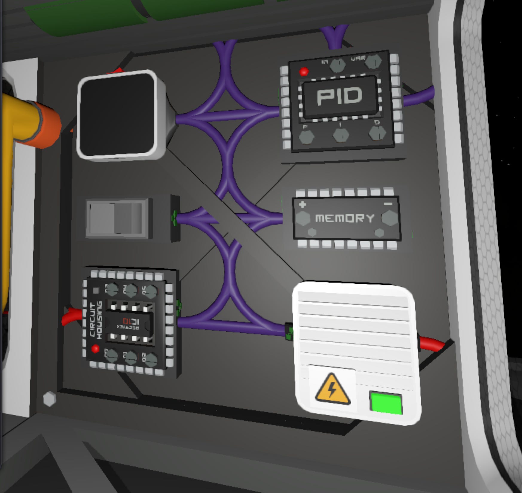
Connect purple cable from the output of the THERM-LL area power controller to the following devices:
Turbo Volume Pump (Data only)
IC Housing (Data only)
Digital Valve
PID Controller (all connections)
Gas Sensor
Logic Switch
Logic Memory
Pressure Regulator
Console (optional)
THERM-BKP Area Power Controller (input)
Insert a small battery into the THERM-BKP area power controller
Turn on network device and ensure active power flow to the THERM-BKP APC junction
THERM-BKP (Battery Cell Small)
Connect cable from the output of the THERM-BKP area power controller to the following devices:
Turbo Volume Pump (Power only)
IC Housing (Power only)
Logic Initialization and Deployment
Thermostat Controller
The thermostat controller manages cooling capacity through two distinct operating modes selectable via manual logic switch. The controller monitors local temperatures and modulates the cooling system’s response based on the active mode selected.
Functional Overview
Monitors PID Controller output to determine required cooling capacity
Manages the circulation of gas into and out of the radiation pipe segment
Mode 0 - Thermal Tracking Mode (875 W Max)
Maintains precise temperature control around a setpoint
Modulates pump speed with respect to required cooling capacity
Mode 1 - Thermal Pulse Mode (75 W Average)
Operates as a bang-bang controller with upper and lower temperature thresholds
Opens valve when temperature exceeds upper threshold
Closes valve and evacuates radiation pipe when the temperature drops below the lower threshold
Hardware Interface
d0: PID Controller
d1: Temperature Setting (K)
d2: Operating Mode (0/1)
Configuration Parameters
PGainTTM (Thermal Tracking Mode - Proportional Gain): -0.0106
IGainTTM (Thermal Tracking Mode - Integral Gain): -0.00003
DGainTTM (Thermal Tracking Mode - Derivative Gain): 0.05
MinTTM (Thermal Tracking Mode - Minimum): -1
MaxTTM (Thermal Tracking Mode - Maximum): 1
PGainTPM (Thermal Pulse Mode - Proportional Gain): 0.2
IGainTPM (Thermal Pulse Mode - Integral Gain): 0
DGainTPM (Thermal Pulse Mode - Derivative Gain): 0
MinTPM (Thermal Pulse Mode - Minimum): 0
MaxTPM (Thermal Pulse Mode - Maxumum): 1
Device Mapping
Each unit must include:
Digital Valve: Circulates gas into the radiation pipe segment
Turbo Volume Pump: Regulates the flow rate of gas through the radiation pipe segment
Procedure
Checks the powered state of the PID. If not powered, the controller goes into standby and resets once the PID is active
Checks the operating mode. If the mode changes, the system resets.
Checks the temperature setting. If the temperature changes the system resets.
Thermal tracking: accumulates the PID output and uses it to compute the pump flow rate
Thermal pulse: reads the Proportional output and uses it to compute the activation state of the valve
System reset: Closes the valve and evacuates the radiation segment
Deployment Checklist
Confirm the following before activating any logic controlled systems. This ensures that the IC program is properly mapped.
Atmospheric Charge
Pressurize the convection pipe with 13.011 mols of carbon dioxide.
Device Labels
Convenience Labels (Recommended)
These device names are not used by the logic controller, but make configuring and troubleshooting easier.
THERM-[AREA]THERM-LLTHERM-BKPMEM-TEMPERATURE-SETTINGSWITCH-THERMOSTAT-MODETHERMOSTATCooling Load Display
Power System Validation
Power on all network junctions
Configure graph display console to capture readings from the Thermostat (IC Housing)
Turn on the PID controller and configure it to read from
GasSensor.TemperatureManual Shutdown Protocol: To turn off the system, turn off the PID Controller first. When the thermostat recognizes this controller as inactive it will automatically evacuate the radiation pipe.
IC10 Chip Installation
Install the IC10 program into the logic-capable device
Final Hold
Do not turn on controller until full startup sequence has been completed and all systems are confirmed.
System Activation and Handoff
System components, logic device, and power domains are now installed and configured. The system is structurally complete, and control logic is staged for deployment.
However, final logic activation must not proceed until all runtime behaviors have been individually validated and the Readiness Procedure is complete.
Final Preconditions for Runtime Handoff
The system must meet the following conditions before control can be handed off to automated logic:
All IC10 programs are loaded onto the connected computer
Logic files should be saved and flashed with the controller off, allowing for isolated verification of supporting systems.
Console properly displays thermostat cooling load
Displays cooling load when the system is in thermal tracking mode that will allow for validation and debugging.Pipe network is charged with the target system moles
Requires approximately 13.011 moles for max cooling capacity.
Proceed to: System Readiness Plan
Next Steps
With greenhouse thermal management enabled, the base now has characterized heat loads, established cooling infrastructure patterns, and proven capacity assessment methodology.
This foundation enables expansion in three critical areas:
Portables Pressurization and EVA Support — The main gas line network provides distribution capacity for suit recharging stations and portable tank filling. This expansion will cover container safety protocols and pressurization procedures for operational mobility.
Monitoring and Alerting — The console and sensor infrastructure established here supports automated monitoring systems. Future modules will integrate alerting protocols and safety response automation.
Power Standardization — As electrical loads increase and diversify, power distribution requires systematic capacity planning and demand management strategies. Future modules will address load shaving techniques, multi-zone distribution architectures, and opportunistic high-performance networks that capitalize on solar storm energy surpluses for batch processing and energy intensive operations.
Content developed in collaboration with Anthropic’s Claude, used for technical documentation structure, engineering analysis, and editorial refinement.