
Life Support Systems Engineering
Design Methodology and Infrastructure Planning for Atmospheric Systems in Stationeers
Introduction
Atmospheric systems require coordinated management of gas composition, pressure regulation, and power distribution to maintain habitable environments in the vacuum of space. The primary engineering challenge stems from the temporal mismatch between steady-state atmospheric needs and instantaneous correction demands, which can vastly multiply power requirements during routine atmospheric events.
This architecture examines atmospheric infrastructure design principles for lunar base operations, including ventilation configurations, sector efficiency optimization, and load leveling networks. These systems address the fundamental constraint that sizing power generation for worst case instantaneous loads results in vastly oversized systems that operate at minimal capacity over 99% of the time. Load leveling uses power regulation and energy storage to manage peak atmospheric demands while maintaining baseline life support conditions in the harsh lunar environment.
Atmospheric Infrastructure
Sectors represent atmospheric boundaries managed by a single environmental control system, measured in Grid Units (GU)—8 m3 building blocks that measure 2m × 2m × 2m—which may encompass multiple rooms with shared atmospheric requirements. Pressure stabilization operates through two distribution tiers: the Main Gas Line, which propagates gas throughout the entire atmospheric grid, and Local Gas Lines provide buffered storage for guaranteed supply while offering burst protection for infrastructure safety.
Distribution and Exhaust Architecture
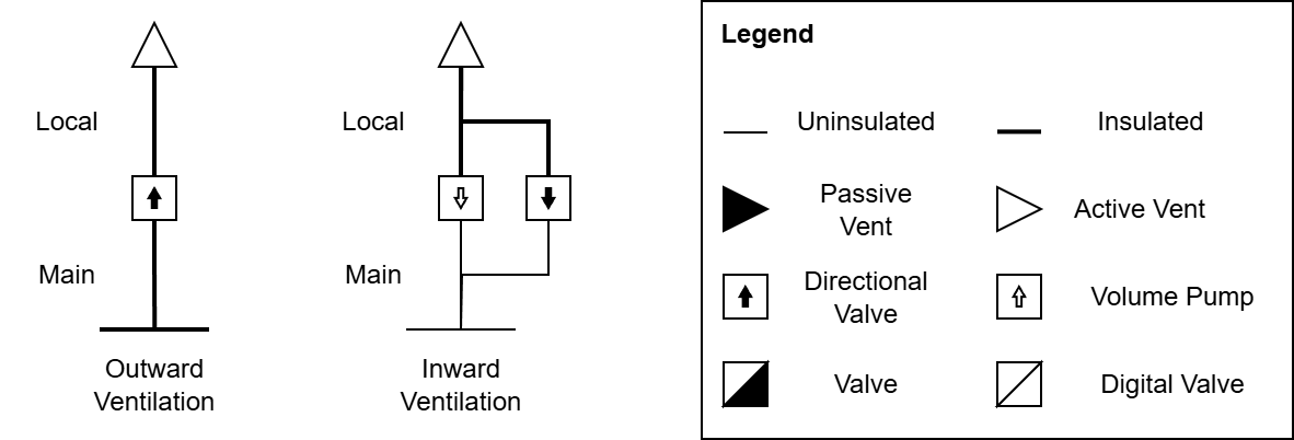
Outward (environmental pressurization) and Inward (exhaust capture) gas management employ fundamentally different operational approaches, but serve complementary infrastructure purposes. Outward systems utilize passive gas delivery for atmospheric pressurization, while inward systems require redundant active management for waste evacuation and infrastructure safety.
Outward systems focus on atmospheric pressurization through passive gas delivery and distributed storage management. Active vents operate at fixed capacity (80 MPa·L maximum) regardless of line pressure, with performance determined by equipment specifications rather than pressure differentials.
Line pressure serves as the primary mechanism for surplus gas storage throughout the pipe network. Higher line pressures enable greater gas inventory within the distribution infrastructure, supplying reserves that provide operational resilience during interruptions or emergency scenarios.
Directional valves ensure guaranteed access to stored gas during peak atmospheric events. This passive approach relies on pressure-driven gas delivery rather than active flow control, with the pipe serving as buffered storage for each connected vent. During surplus conditions, pipes can maintain additional gas inventory, ensuring that an individual local line or main line failure does not eliminate atmospheric restoration capability for the rest of the system.
Inward systems prioritize burst risk mitigation and infrastructure safety near structural elements. Directional valves support normal operations where main gas line pressure remains below 80% burst capacity limits, providing passive evacuation capability during routine atmospheric management. Volume pumps provide active evacuation when local pressure exceeds safe operational thresholds, ensuring that high-pressure scenarios cannot compromise base structural integrity or create simultaneous pipe failure and base decompression events.
Both outward and inward systems require precise control logic to coordinate active operations, ensuring optimal performance while maintaining safety thresholds throughout the atmospheric infrastructure.
Control Systems
Atmospheric infrastructure requires coordinated control systems to manage environmental conditions, equipment operation and safety protection. The mixture-pressure controller (mix-press) manages both waste pump operations and ventilation controls through functionally distinct but integrated operational behaviors.
Waste Pump Control
The waste pump system manages active evacuation of waste gases to maintain safe local pipe conditions and prevent structural hazards. This system monitors pipe pressure conditions and evacuates gases once the system exceeds safety thresholds.
Ventilation Control
The ventilation system manages sector pressure and composition through sequential vent activation. Rather than operating multiple vents simultaneously, the system activates them one at a time to stabilize power consumption and achieve target atmospheric conditions. Waste ventilation receive priority over pressurization, ensuring that safety-critical evacuation takes precedence during concurrent operational demands.
This sequential approach maintains system effectiveness while operating within power budget constraints, extending operational duration rather than increasing peak power consumption during atmospheric corrections.
Baseline Costs and Energy Efficiency
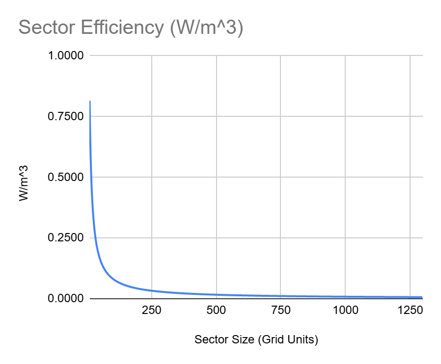
Atmospheric system efficiency exhibits an inverse relationship with sector size, creating fundamental tradeoffs between infrastructure consolidation and operational costs. Power consumption per cubic meter decreases dramatically as sector volume increases, with small compartments suffering severe efficiency penalties from fixed baseline overhead requirements. Understanding these scaling relationships is critical for optimizing habitat design, as the decision to consolidate or partition sectors directly impacts long-term energy budgets and system complexity.
Energy Cost Distribution
System energy analysis reveals that baseline costs account for 99.9% of total daily energy consumption, with ventilation operations contributing only 0.1% to overall power requirements. The max 65 W sensor and controller overhead per sector creates fixed energy costs that dwarf energy consumption during normal operational scenarios where atmospheric adjustments occur infrequently.
This distribution pattern means that ventilation scaling provides negligible energy costs during normal atmospheric operations where adjustments are purely driven by respiration rates and can be completed within a few seconds. Events that alter normal operational patterns—such as airlock cycling, broad temperature fluctuations, or contamination scenarios—can significantly affect these energy characteristics by requiring extended equipment operation beyond brief respiration-driven adjustments.
Optimization Implications
The baseline cost structure creates significant scaling penalties for multi-sector configurations that multiply fixed infrastructure costs without proportional benefits. Each additional sector requires dedicated sensor and controller infrastructure, creating linear cost scaling that quickly overwhelms any operational advantages from atmospheric compartmentalization.
Sector consolidation represents the primary energy optimization opportunity by distributing fixed baseline costs across maximum atmospheric volume. Each additional sector requires dedicated sensor and controller infrastructure, creating linear cost scaling. For example, three 10 GU sectors consume 195 W in baseline costs compared to a single 30 GU sector consuming 65 W for equivalent atmospheric volume management. Large sectors with internal physical divisions maintain single controller infrastructure while providing equivalent functional space organization, eliminating redundant baseline costs without sacrificing operational flexibility.
Load Leveling Network Architecture
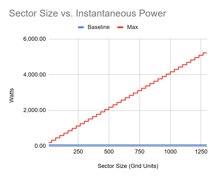
The fundamental challenge in atmospheric system design lies in the temporal mismatch between power generation cycles and atmospheric demand patterns. While baseline control systems for a 10 GU space start at 65 W, peak atmospheric corrections create instantaneous demands at 198 W, representing a 3x increase over normal operation.
Temporal Power Management Strategy
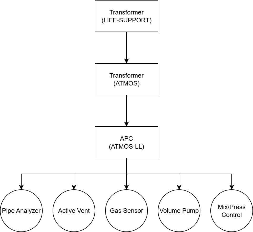
Most atmospheric corrections are brief but occur on the order of minutes. A specialized power architecture enables temporal power management—limiting power throughput to average rates while storing energy over time to handle peak demands. This load leveling network consists of two critical components working in series:
Transformer (Power Regulation): Limits the instantaneous power draw from the main electrical grid to sustainable levels, typically sized for baseline atmospheric loads plus a safety margin. This prevents atmospheric systems from overwhelming power generation during peak events.
APC (Energy Storage): Provides local energy buffering that accumulates power over time and releases it during high-demand atmospheric events. This storage capacity must be sufficient enough to support the energy demand required for a full atmospheric correction cycle.
Network Characteristics
The load leveling network alters system design priorities from instantaneous power optimization to energy management over time. This approach exhibits several operational characteristics:
Power System Decoupling: Peak demands operate independently from main power generation through local energy buffering. Power systems can be sized for average loads while peak demands are satisfied through stored energy.
Regulated Load Characteristics: The transformer creates power draw patterns that remain constant regardless of downstream activations. This regulation simplifies power system planning and eliminates load balancing complexity across multiple systems within the same power grid.
Energy Storage Dependencies: Local energy storage capacity determines the duration and intensity of atmospheric events that can be sustained. APC battery capacity drives operational limits for peak power scenarios and informs sector sizing limits.
The load leveling network requires dedicated regulation and storage infrastructure for each sector. The energy storage capacity of this infrastructure becomes a primary constraint in determining appropriate sector sizing and atmospheric systems design parameters.
Sector Sizing Methodology
Sector sizing requires balancing operational requirements within energy storage and electrical infrastructure constraints. This methodology provides a systematic approach for calculating sector configurations based on gas consumption patterns and load leveling network capacity.
Define Operational Parameters
Room Pressure: Target operational pressure for the sector (100 kPa for habitable environments). This determines the total gas volume required for full pressurization.
Atmospheric Composition: Target gas ratios for the operational environment. For typical habitable sectors:
20% O2 (oxygen for respiration)
77% N2 (inert atmospheric buffer)
2% CO2 (sufficient for plant growth)
<1% Others (contaminant tolerance + composition margin)
The “Others” category serves dual purposes: providing tolerance for atmospheric contaminants while maintaining operational margin for composition control. Targeting exactly 100% with O2, N2, and CO2 eliminates operational flexibility since precise ratio maintenance is impractical during normal atmospheric management.
Room Temperature: Operating temperature for atmospheric calculations, affecting gas density and correction energy requirements.
Gas Consumption Rate: Total atmospheric consumption from all sources including crew respiration, plant photosynthesis cycles, and livestock metabolic requirements. This determines atmospheric drift rate and correction frequency.
Establish Hard Operational Constraints
Energy Storage Limit: Battery capacity establishes the energy budget for load leveling network operation. Large battery provides 288 kJ capacity, while Nuclear battery provides 2.3 MJ capacity. The load leveling network uses battery storage to manage power delivery between baseline and peak correction modes.
Line Pressure Limit: Maximum safe operating pressure before pipe burst risk. Pipe burst occurs at 60,795 kPa, but operational limits should be set around 80% of this threshold (48,636 kPa) for safety margins.
Flow Rate Minimum: Minimum target pressurization rate for the sector. Set to 0.3 kPa/sec (see Appendix A3. Dynamic Displacement Calculations).
Calculate Energy Budget
Sector sizing requires calculating the total energy demand for one complete correction cycle within the load leveling network.
Correction Interval and Duration
Correction Interval: Time between atmospheric corrections, determined by gas consumption rate and atmospheric drift patterns. Higher gas consumption creates shorter intervals between required corrections.
Where:
I = correction interval
ΔR = gas ratio surplus to be consumed (see Appendix A3. Dynamic Displacement Calculations)
P = room pressure (kPa)
S = room size (GU)
T = temperature (K)
M = respiration rate (moles/second)
Correction Duration: The time required for each correction can be determined by the Dynamic Displacement Calculations.
Power Components
Baseline Power: Continuous power consumption for sensors and controllers. Operates continuously within the load leveling network regardless of correction activity.
Ventilation Power: Power consumed during atmospheric corrections through sequential vent operation. Based on room size and vent requirements, with larger rooms requiring more vents but corrections taking the same duration.
Each active vent moves 80 MPa·L/tick. To achieve flow rate limit of 0.3 kPa/tick for habitable sectors, vents are scaled in multiples of 33 GU for control efficiency:
1-33 GU: 1 outward vent per gas type
34-66 GU: 2 outward vents per gas type
67-100 GU: 3 outward vents per gas type
Ventilation power is calculated as:
Where:
S = room size (GU)
Fmin = minimum flow rate (kPa/tick)
Waste Removal Pump Power: Power consumed by pumps ensuring waste evacuation during restoration. Waste removal power scales based on room size, flow rate and waste buffer volume requirements. Operates intermittently during atmospheric corrections with a max 50% duty cycle during active corrections.
The waste removal system operates on two pressure thresholds: the Pipe Safety Threshold activates the pump and the Pipe Maximum throttles inward vent intake. Smaller pressure margins require less pump power and larger buffer volumes, while larger pressure margins require more pump power and smaller buffer volumes.
Minimum buffer volume:
Waste removal pump power:
Where:
Vbuffer = buffer volume (L)
Psafety = pipe safety pressure (kPa)
Pmax = pipe pressure maximum (kPa)
F = max flow rate (kPa/tick)
S = room size (GU)
Max Power: Peak power consumption during atmospheric corrections, including baseline systems and active correction equipment (vents, pumps, controls)
Max Power = Baseline Power + Ventilation Power + Waste Removal Pump Power
Total Energy and Load Sizing
Total Energy: The load leveling network must store sufficient energy for one complete correction cycle.
Total Energy = (Baseline × Correction Interval) + (Max - Baseline) × Correction Duration
Where:
Baseline × Correction Interval = energy to sustain continuous systems between corrections.
(Max - Baseline) × Correction Duration = additional energy for correction equipment operation
Load Sizing: Set the transformer power limit to Total Energy ÷ Correction Interval. This determines the average power delivery rate needed to recharge the load leveling battery between correction cycles.
Links to Implementation
For operators ready to implement an Atmospheric Control system within their own base, the following implementation guides walk through the full construction process—complete with layout considerations, materials, and programmable logic:
Life Support I: Base Pressure and Composition - Complete build guide covering sector control implementation, load leveling network setup, and system integration with existing atmospheric recovery infrastructure.
Life Support II: Base Expansion - Safe compartment expansion procedures for controlled pressurization and sector integration. Covers vestibule design, interconnect plumbing installation, pressure safety controller setup, and operational capacity accounting for scalable base growth.
Life Support III: Radiative Cooling - Construction guide for deploying a Dedicated Thermal System (DTS) in a starter greenhouse environment. Covers physical installation, power network configuration, gas pressurization, and how to interpret PID signals for operational capacity assessment.
Life Support IV: EVA Portability - EVA infrastructure guide covering automated suit charging, configurable canister fills, waste recovery, and IC10 controller deployment for portable gas systems.
Appendix
A1. Glossary
Atmospheric Correction — The process adjusting gas composition and pressure to meet target thresholds
Baseline Power — Continuous power consumption for sensors and controllers
Dynamic Displacement — Variable gas correction approach based on composition deviation
Sector — Area managed by a single environmental control system, which may encompass multiple rooms or spaces with shared atmospheric requirements.
Flow Rate Limit — Maximum achievable flow rate derived from the number grid units per active vent type, determining optimal vent scaling for atmospheric control efficiency.
Grid Unit (GU) — 8 m³ building block measuring 2m × 2m × 2m, used as the standard unit for atmospheric volume calculations.
Inward Systems — Gas management infrastructure that prioritizes burst risk mitigation and infrastructure safety, handling waste gas evacuation and atmospheric removal.
Line Pressure — Operating pressure in gas distribution lines, affecting pump energy consumption and burst risk.
Load Leveling Network — Power regulation and energy storage system using a transformer and APC in series to manage temporal power mismatches between baseline and peak atmospheric demands.
Local Gas Line — Secondary distribution tier providing buffered storage for guaranteed gas supply and burst protection for individual sectors.
Main Gas Line — Primary distribution tier that propagates gas throughout the entire atmospheric network.
Mixture-Pressure Controller (mix-press) — Control system managing sector atmospheric conditions by coordinating vent operations to maintain target pressure and gas composition.
Outward Systems — Gas management infrastructure focused on atmospheric pressurization, maintaining target local storage, and minimizing reliance on main gas lines during emergency scenarios.
Peak Atmospheric Events — High power demand scenarios including airlock cycling, contamination response, atmospheric corrections, and rapid pressurization that require increased energy consumption above baseline operations.
Pipe Safety Threshold — Pressure level that triggers waste pump activation
Sequential Vent Operation — One-at-a-time vent activation strategy used to limit peak energy usage.
Temporal Power Management — Energy strategy using regulation and storage to handle brief peak demands rather than sizing power generation for worst-case instantaneous loads.
A2. Active Vent Flow Rate Calculations
Active vents operate on localized pressure differentials rather than room-wide pressure conditions. Understanding this behavior is essential for achieving target flow rates and optimal system performance.
Local Pressure Dynamics
An active vent pulls gas exclusively from the Grid Unit (GU) where it is physically located. This creates a pressure change in that specific cube before pressure equalizes across the entire room space.
This localized behavior means that vent performance cannot be calculated using room-wide pressure differentials, despite the intuitive expectation that maximum pump capacity (80 MPa·L/tick) would be achieved through total space pressure calculations.
Flow Rate Calculation
To achieve target flow rates, the pressure external setting must account for localized pressure dynamics and pressure equalization across the room volume.
Target Flow Rate Formula:
Where:
Proom = current room pressure (kPa)
F = target flow rate (kPa/tick)
S = room size (GU)
V = number of vents of the same type
± = addition for outward flow, subtraction for inward flow
min()= minimum value between calculated differential and 10 kPa limit
Application Guidelines
Outward Flow (Atmospheric Pressurization):
Inward Flow (Waste Evacuation):
The 10 kPa limit represents the maximum flow rate that a vent can achieve: 10 kPa/tick for an 8000 L cube (1 GU).
Multiple Vent Scaling: The V term accounts for multiple vents of the same type operating simultaneously. Each additional vent reduces the pressure differential required per vent to achieve target total flow rate.
This formula ensures that vent pressure settings align with the localized pressure dynamics of cube-level gas extraction and room-wide pressure equalization, enabling predictable flow rate regardless of room size or vent configuration.
A3. Dynamic Displacement Calculations
Atmospheric corrections use variable gas displacement based on composition deviation from target ratios rather than fixed flow rates. This dynamic approach ensures efficient, predictable convergence to target atmospheric composition while preventing overcorrection cycles.
Dynamic Displacement Formula
The displacement for each gas correction is calculated using:
Where:
D = calculated displacement for the gas (kPa)
Rtarget = target ratio for the gas (decimal)
Rcurrent = current ratio for the gas (decimal)
P = target room pressure (kPa)
Dmin = minimum gas displacement threshold (0.3 kPa)
Constraint: Rtarget ≥ Rcurrent
Gas Ratio Updates
After each correction displacement, gas ratios are recalculated based on the gas that is added:
Increasing Gas Ratio:
Decreasing Gas Ratios:
Where:
r = updated gas ratio
r0 = initial gas ratio before correction
P = room pressure
D = correction displacement
The correction process iterates through these calculations with convergence behavior determined by the Dmin threshold. The 0.3 kPa minimum displacement is calibrated to achieve convergence within two corrections for 3-gas mixtures with 1% tolerance threshold. Higher tolerance thresholds likely support higher minimum displacement values.
Minimum Displacement Threshold
The Dmin value of 0.3 kPa allows targeted gas adjustments without oversaturating other gas ratios in the atmospheric mixture. If set too high, adjustments would endlessly dilute each other without reaching equilibrium. If set too low, microscopic adjustments would require more frequent correction cycles without meaningful efficiency gains.
A4. References
Reddit. Active Vent Flow Rate Test Results https://www.reddit.com/r/Stationeers/comments/1mo9zxf/active_vent_flow_rate_test_results/
Steam Community. Human Consumption Values Discussion https://steamcommunity.com/app/544550/discussions/0/1693785035812235337/#c1693785035812644007
Reddit. Plant to Player Ratio Discussion https://www.reddit.com/r/Stationeers/comments/138trbf/whats_the_ratio_of_plants_per_player_for/
Stationeers Wiki. EVA Suit https://stationeers-wiki.com/EVA_Suit
Stationeers Wiki. Farming Guide https://stationeers-wiki.com/Guide_(Farming)
Stationeers Wiki. Chicken https://stationeers-wiki.com/Chicken
Changelog
October 2025 - Ventilation Optimization
Updated ventilation scaling from 10 GU to 33 GU per ventilation set
Minimum effective pressurization rate: 0.3 kPa/sec (down from 1 kPa/sec)
Gas sensor placement: 1 per 10-11 GU
Benefits: reduced infrastructure requirements, lower power consumption, support for larger sectors
Migration strategies for existing builds:
Expand without additions: Existing ventilation supports up to 30 GU without additional infrastructure
Passive decommission: Close valves to dedicated gas lines, allow system to gradually empty pipes
Active reclaim: Replace valve with pipe, disassemble to push gases back into main line
Content developed in collaboration with Anthropic’s Claude, used for drafting, editing, and technical validation.