
Life Support II: Base Expansion
Safe compartment expansion procedures for controlled pressurization and sector integration.
Note for independent readers: This document assumes prior familiarity with the architectural principles and subsystems outlined in the broader Stationeering Systems framework. Readers seeking system-level rationale or integration context are advised to consult the foundational document Life Support Systems Engineering for comprehensive design overview.
Prerequisites
Atmospheric distribution system (see Life Support I)
Adequate gas supply for pressurization
Objectives
Safely pressurize new atmospheric compartments within tolerable survivability constraints
Constraints
Maintain base atmospheric pressure between 80-100 kPa to ensure a minimal oxygen partial pressure of 16 kPa
Pressurization rate of new areas from existing compartments cannot exceed 0.3 kPa per second to allow the control system to effectively compensate for the pressure loss
Expansion Workflow Overview
The base now has working power, atmospheric reclamation, and pressurization systems. The next phase requires farming for food production and specialized workshop areas. Adding these capabilities means constructing new pressurized compartments within the sector. Safe expansion requires controlled pressurization procedures that protect crew and plant life while integrating new spaces into the base atmosphere.
What Gets Built?
New compartments are added through:
Structural construction (45 min/compartment) — frames, walls, and foundations that define new spaces
Atmospheric integration (90 min/vent group1) — expanding pipe network and flow capacity to maintain 0.3 kPa/sec regulation rate, then a gradual pressurization that allows atmospheric systems to compensate for volume changes
Each addition follows the same safe expansion pattern: build, seal, pressurize, integrate.
Why Now?
Farming systems require dedicated spaces with thermal regulation. Extended EVA operations impact hygiene and morale, making interior workspace expansion a practical necessity. Without controlled pressurization procedures, adding new compartments risks rapid decompression that can kill crew and plants.
Materials and Components
Required components vary based on compartment size and configuration.
Reusable Equipment
- 1 IC Housing
- 1 IC10
- 1 Digital Valve
- 2 Passive Vents
- Pipe
- Cable Coil (Heavy)
Per-Compartment Build
- 1 Gas Sensor
- Cable Coil (Heavy)
- Frames (Iron/Steel)
- Walls
Atmospheric (if additional capacity needed)
- 4 Active Vents
- 12 Insulated Pipe Utility Kit
- 3 Pipe Meter
- Insulated Pipes
Example
The corridor expansion shown uses the following materials:
* This corridor includes an emergency exit (manual airlock) - see future safety systems documentation for emergency egress design
Vestibule Design
New compartments connect to existing base infrastructures through vestibules—1 GU transition spaces that enable safe pressurization and future operational flexibility. These spaces serve multiple functions: immediate connection points during expansion, mounting locations for atmospheric equipment, and adaptable spaces that can be converted from open passages to bypass doors or full airlocks as operational needs evolve.
Spatial Requirements
Vestibules must align with the main gas line clearance area to enable atmospheric infrastructure integration. This 6-meter zone is measured from existing transition spaces and houses the main gas distribution network that supplies all base compartments.
Infrastructure Access
Proper wall placement ensures adequate space for mounting atmospheric equipment as the new compartment requires it:
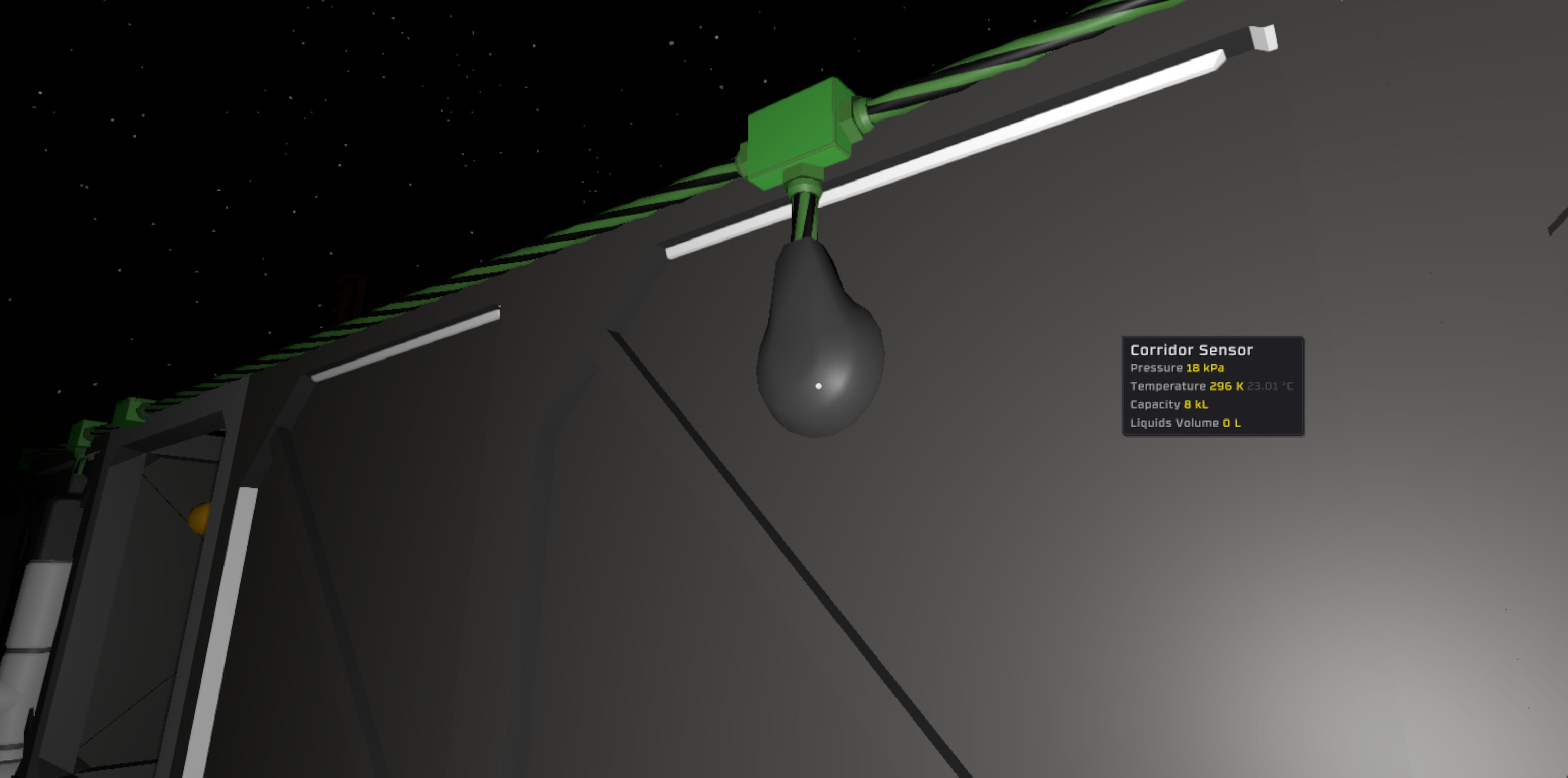
Gas sensor for atmospheric monitoring
Active vents (if capacity expansion needed) for pressurization and exhaust management
Pipe connections to the gas distribution network
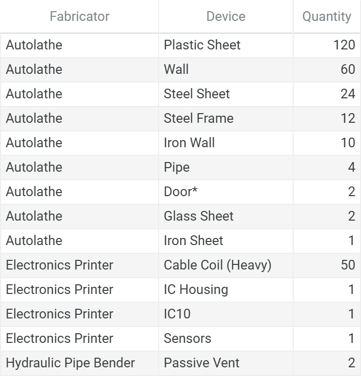
This design accommodates future infrastructure additions without requiring structural modifications. Frame areas adjacent to the vestibule house interconnect plumbing, following the same pattern as airlock construction, but uses a passive-to-passive vent configuration with a digital valve for controlled gas flow between spaces.
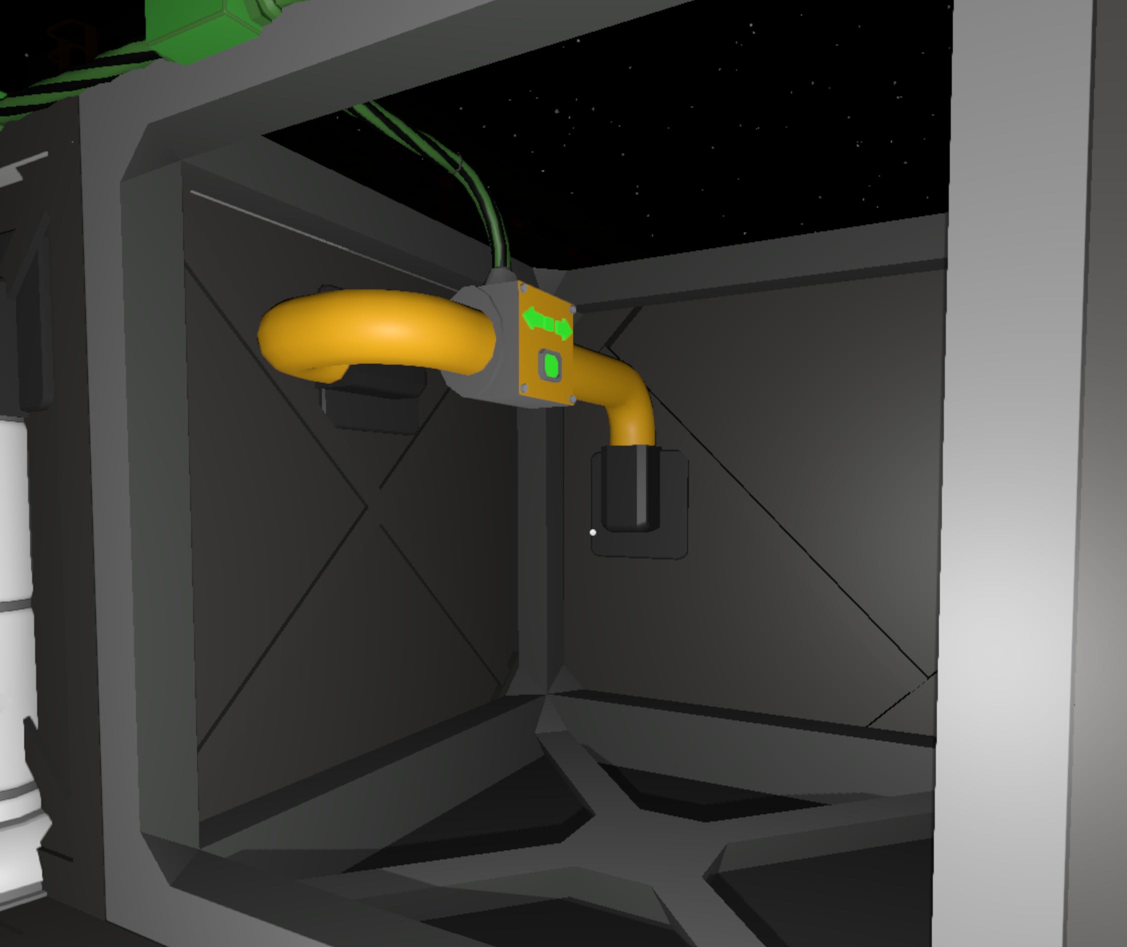
Example Configuration
The example shows a 5x2 GU corridor added to an existing 3x3 GU entryway. The vestibule connects the two spaces while maintaining alignment with the gas line clearance.
Design Flexibility
Vestibules can be configured based on immediate needs and future requirements:
Open passage: Maintains atmospheric continuity between compartments (current implementation)
Bypass door: Enables joining or separating two sectors with compatible atmospheres
Airlock: Provides complete atmospheric independence between compartments with separate environmental control
The initial construction establishes the spatial framework that supports any of these configurations without requiring major structural modifications.
Calculating Sector Capacity
After pressurization completes, the sector’s operational capacity must be updated to reflect the new volume. This capacity is used to optimize ventilation efficiency within the mix-press control system.
Operational Volume Formula:
Include in operational volume:
New compartment space
Open vestibules (continuously managed atmosphere)
Exclude from operational volume:
Airlocks (isolated when closed)
Manual airlocks (doors typically closed, gas isolated)
Bypass doors (shared between sectors, not counted toward either)
Example (corridor expansion)
Existing sector: 9 GU (3x3 entryway)
New corridor: 10 GU (5x2)
Open vestibule: 1 GU
Airlock: 1 GU (excluded)
Manual Airlock: 1 GU (excluded)
Updated operational capacity: 9 + 10 + 1 = 20 GU
This capacity value is used during deployment to update the size setting on the mix-press controller, ensuring proper regulation of the expanded sector.
Logic Initialization and Deployment
Interconnect Controller
The Interconnect controller allows for the safe pressurization of new atmospheric compartments and is connected directly to the LS-ATMOS-LL power network.
Functional Overview
Opens the interconnect valve to allow gas flow from pressurized area to unpressurized compartment
Closes the interconnect valve if source pressure drops below safety threshold (monitors all sensors labeled ‘Sector’), protecting base atmosphere
Closes the interconnect valve and powers down when target pressure is reached in new compartment
Hardware Interface
d0: Pressure kPa (Memory)d1: Gas Sensor (new compartment)d2: Digital Valve (interconnect valve)
Configuration Parameters
- PressureTolerance (Pipe Pressure Deviation kPa): 5
- Local (label): “Sector”
Deployment Checklist
Confirm the following before activating the interconnect controller. This ensures that the IC program is properly mapped.
Runtime-Required Labels
These labels must match exactly for devices within atmospheric compartments currently integrated within the sector:
SectorSectorCarbonDioxideSectorNitrogenSectorOxygenSectorExhaust
Do not apply these labels to devices within unintegrated compartments until pressurization is complete.
Convenience Labels (Recommended)
Provide a unique name to the gas sensor and digital valve to ensure proper configuration of components, examples:
Corridor SensorCorridor Valve
Seal Verification
Briefly open and close the target valve
Monitor the target gas sensor to ensure pressure retention
IC10 Chip Installation
Install IC10 program into the logic-capable device
Update the device inputs to read from the pressure setting, target sensor and target interconnect valve.
Final Hold
Do not turn on controller until the full startup sequence has been completed and all systems are confirmed.
System Activation and Handoff
System components, logic device, and power domains are now installed and configured. The system is structurally complete, and control logic is staged for deployment.
However, final logic activation must not proceed until all runtime behaviors have been individually validated and the Readiness Procedure is complete.
Final Preconditions for Runtime Handoff
The system must meet the following conditions before control can be handed off to automated logic:
All IC10 programs are loaded onto the connected computer
Logic files should be saved and flashed with the controller off, allowing for isolated verification of supporting systems.
All devices are labeled and mapped per controller requirements
Includes runtime (e.g.,
Sector) and convenience labels (e.g.,Corridor Sensor) for accurate logic targeting and flashing.Atmospheric compartment is properly sealed
Gas sensor shows pressure retention
Proceed to: System Readiness Plan
Content developed in collaboration with Anthropic’s Claude, used for technical documentation structure, engineering analysis, and editorial refinement.
Additional ventilation infrastructure required when sector capacity exceeds limits defined in Life Support Systems Engineering