
Automated Terminal Sequencing for Orbital Trade Operations
A composable control architecture for contact qualification, pad assignment, and automated calldown
Introduction
Lunar trade economics revealed that fuel trade opportunities average around once every 2 minutes. This frequency precludes manual operation as a viable long-term strategy. Automated traffic management closes that gap: given a set of locked contacts, it evaluates inventory, assesses pad availability, determines call-down feasibility, and executes landing without operator intervention.
Landing a trader is an expensive operation. Dish movement, signal interrogation, and contact time represent a meaningful draw on power and time budgets—with power requirements measured in kilowatts. That means a system cannot commit to landing a contact that it cannot complete.
Thus, traffic management is broken down into four verticals:
Tracking focuses on acquiring signal and positional data of all available contacts and exposing that information to all subsequent verticals
Opportunity alignment evaluates each contact against operator-defined trade criteria to determine whether a viable exchange exists
Pad clearance assesses landing pad availability and compatibility to assign an appropriate terminal to a qualified contact
Dispatch coordinates the full call-down sequence, incorporating feasibility analysis and dish movement before committing to a landing
System Patterns
Three component types recur across the four verticals. Understanding what each one does and how it is accessed removes ambiguity as it appears in different contexts.
A registry maintains an indexed list of device reference IDs and exposes them through the stack. The registry is accessible by channel, allowing any IC on the network to retrieve a device reference without holding a direct device connection.
A resolver responds to a query against the selected contact slot. It loads state, evaluates against its criteria, and writes the result to the Setting register. Callers batch read across all resolvers simultaneously using the Maximum aggregator to retrieve the best result.
A calculator performs independent computations that would otherwise exceed the instruction budget of a single IC. It may read from multiple data sources and store the result in its stack by contact slot index. The device’s Setting register stores the most recently updated slot request.
Data Synchronization
Each device operates asynchronously and may not update its output by the time the value is read. Without a mechanism to verify freshness, there is a risk in consuming a result that is computed for a previous request.
To eliminate this ambiguity, controllers encode the contact slot index into their Setting register, known as a slot response. The consumer compares that value against the input before consuming the result. If the indices do not match, it retries indefinitely.
For resolvers to use this convention, a boolean qualifier (whether or not a slot meets the specified criteria) is also encoded along with the slot. The slot is stored in the lower byte while the qualifier flag occupies the higher byte:
QUALIFIER_FLAG = 1
CONTACT_SLOT_INDEX = 2
SETTING = $0102 (258)
Because the qualifier flag occupies the most significant position, a matching result numerically dominates any non-matching result. The Maximum batch read therefore returns the correct result automatically with no additional filtering needed.
Architecture Overview
Dishes are the primary data type shared between components. Registries store references to dishes, and other components consume from them. The following diagram illustrates the component layout across all four verticals. Some dishes serve dual purposes across vertical boundaries—indicated by dashed borders—and are discussed within the relevant sections.
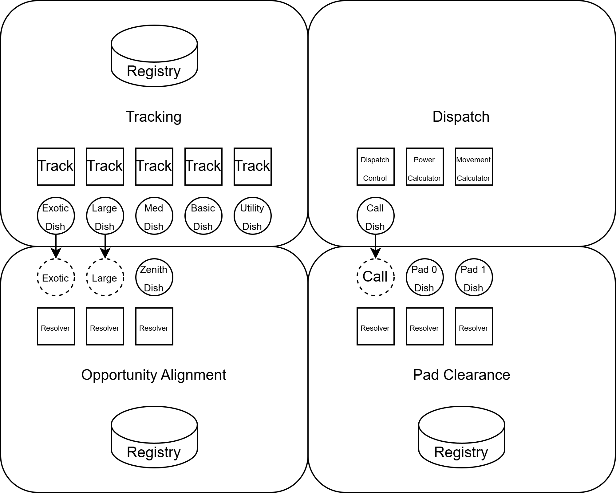
Tracking
Tracking is the foundational data layer for the traffic management system. It maintains positional lock on all five contact slots and exposes that data to the other verticals through a shared registry. Construction and configuration of the tracking array is covered in Signal-Domain Contact Acquisition.
The tracking registry maintains the list of tracking dishes and writes their reference IDs to the stack by contact slot index. It is accessible on Channel 0. Any vertical that requires signal or positional data for a given contact reads from this registry directly—it is the single source of truth for contact discovery across the entire system.
Opportunity Alignment
Opportunity alignment determines whether a locked contact represents a viable trade —goods the trader sells, orders the station can fill or both. It is one of the many qualification gates in the call-down sequence. Contacts that do not present an opportunity are skipped without further evaluation.
Using the Dish Stack
Medium and large dishes expose a stack interface that can be queried for trader data—including cargo manifest and open orders. Small dishes do not support this interface. A contact must be visible to the dish for stack queries to return valid data; a locked contact that falls below the visibility threshold will not yield manifest information regardless of positional accuracy.
Zenith Dish
Utility, Basic, and Medium contacts are covered by a single medium dish—the zenith dish—fixed at (H,V) = (0,0) and operated at 2000W. Since small dishes track these contacts for positional lock, but do not support stack queries, making a medium dish is necessary for trader data access. At this configuration all three contact types remain visible at all elevations, with no added dish movement. Actual power draw is 250W—50W base power plus resolution power actualized at 10% of the power setting.
Large and Exotic Dishes
Large and Exotic contacts are handled differently. Their tracking dishes are medium-sized, already maintain visibility on those contacts, and have available stack capacity. Co-opting them for manifest resolution eliminates the need for additional hardware and avoids the latency and mirroring costs of a separate dish.
This co-option is governed by a strict ownership model. Positional and signal assignments belong exclusively to the tracking logic. Stack management belongs exclusively to the resolver. A resolver that reads from any manifest reads trader data from the stack without touching the dish’s pointing state and the tracking IC updates dish position without touching the stack.
One consequence of this boundary is that the zenith dish’s signal assignment cannot be owned by its resolver either. Signal loading for the zenith dish belongs to the manifest registry, which maps the appropriate signal ID from the tracking registry before resolution occurs.
Manifest Registry
The manifest registry maintains the list of manifest dishes and exposes them by contact slot index. It is accessible on Channel 1. When a slot request arrives, the registry reads the corresponding signal ID from the tracking registry and loads it onto the zenith dish. This ensures that the dish observes the correct contact before the resolver queries its stack. For Large and Exotic slots, the registry returns the reference ID of the tracking dish directly, since signal assignment for those dishes is already managed by the tracking IC.
Accessors of the manifest registry use it to read trader data which should occupy addresses 0-2 on the dish stack. This range is reserved across all manifest dish configurations—any resolver implementation must populate these addresses and not write custom data into them.
Manifest Resolver
One resolver runs per manifest dish — one for the zenith dish covering slots 0-2, one for the Large tracking dish, and one for the Exotic tracking dish. Each resolver monitors its dish’s stack, evaluates whether a trade opportunity exists for the current request and writes a qualified result to its Setting register using the resolver encoding described in System Patterns.
Response Encoding
| Position | Field              | Data Type |
|----------|--------------------|-----------|
| 0-7      | CONTACT_SLOT_INDEX | INT_8     |
| 8-15     | HAS_OPPORTUNITY    | BYTE_8    |
The resolver is the primary extensibility point in the opportunity alignment vertical. Any logic that evaluates trader data and returns a compatible result satisfies the contract—including item filtering, requested and available amounts, or any combination of operator-defined criteria. The only hard constraint is that addresses 0-2 on the dish stack must be populated with trader data and not be overwritten by the resolver.
Pad Clearance
Pad clearance determines whether a contact can be assigned to an available landing pad. Contacts without a landing pad assignment are skipped from evaluation.
Pad Dish Array
While dishes have a data field for reading and storing the TargetPadIndex, there is ambiguity in how that maps to the landing pads themselves. To circumvent this, a landing pad is provisioned with a dedicated dish on an isolated data network. Without this, there is no reliable mechanism to guarantee that a call-down routes to a specific pad.
Each landing dish is mirrored onto the primary traffic network where the dispatch can access it. Similar to manifest resolution, the contact only has to be visible to the dish in order to initiate a landing.
Pad Registry
The pad registry maintains the list of landing dishes and exposes them by terminal index on Channel 2. A terminal index is an operator-assigned mapping that identifies landing pads independently of TargetPadIndex. Unlike the tracking and manifest registries, which maintain a list loaded by device pin, the pad registry is externally-populated—each pad resolver registers its own landing dish. This makes the pad count flexible; adding or removing a pad requires no changes to the registry logic itself.
The dispatch loads the appropriate landing dish from the pad registry once a pad assignment is confirmed, then coordinates signal and positional data to that dish before initiating call-down.
Pad Resolver
One resolver runs per pad. Each resolver evaluates whether its pad is available and whether the current contact is compatible, then writes its result to its Setting register using the resolver encoding described in System Patterns.
Because the pad registry uses the Maximum aggregator, the terminal index assignment carries an implicit prioritization. Contacts are routed to the highest-indexed available compatible terminal. Terminals that must remain accessible for contacts with restrictive compatibility requirements—like a pressurized hangar that only an Exotic contact can use—should carry lower indices. This ensures that common contacts preferentially occupy higher-indexed terminals, leaving specialized terminals available when they are needed.
Compatibility criteria are fully operator-defined. A resolver can encode contact type filtering, cargo-specific assignment, atmospheric requirements, or anything else expressible in IC10. The only contract the resolver must satisfy is the data mapping below:
| Position | Field              | Data Type |
|----------|--------------------|-----------|
| 0-7      | CONTACT_SLOT_INDEX | INT_8     |
| 8-15     | TERMINAL_INDEX     | BYTE_8    |
| 16-23    | IS_AVAILABLE       | BYTE_8    |
Dispatch
Dispatch coordinates the full call-down sequence. It consumes the outputs of all three preceding verticals—contact lock state from tracking, trade qualification from opportunity alignment, and pad availability from pad clearance—and executes the sequence that brings the trader to a compatible terminal.
Call Dish
The call dish is a large satellite dish that operates on an isolated power network with a dedicated battery. This separation ensures that the high instantaneous power draw of contact interrogation does not destabilize the station’s primary power grid.
Battery capacity is sized to the worst-case single call-down—maximum watts to contact multiplied by maximum seconds to contact for the most demanding contact type. That would be large and exotic traders with their maximum watts and duration at 8000 W and 600s respectively. That means the worst-case interrogation would consume up to 4.8 MJ supportable by a large station battery at 9 MJ.
The network power level is determined by multiplying the opportunity frequency—derived in Lunar Trade Economics—by the average joules per contact type. Average joules per contact is derived from the tradeable index:1 minimum and maximum watts to contact and seconds to contact are known quantities for each contact type.
Landing Large Contacts
The landing pad array typically uses small dishes to coordinate landing with the trader. However, Large contacts—with their 250 W minimum visibility requirement—would fall outside of the small dish capability. A dedicated medium dish per large trader pad is a valid solution, but carries meaningful overhead: additional hardware, higher power consumption, and slower dish movement relative to the small dish.
Conveniently, the call dish is already positioned on the contact for interrogation, and already maintained by dispatch. Reusing it as the landing dish for large contacts eliminates that overhead entirely. The dispatch assigns signal and positional data to the call dish in its landing role using the same ownership model that governs all other dish assignments in its purview.
Movement Calculator
The movement calculator estimates the net horizontal distance the call dish must travel that is not offset by vertical movement. It stores the result on the controller stack by contact slot index. This value is used to estimate total dish movement time and plan the movement sequence before interrogation begins, allowing the power calculator to produce a more accurate uptime estimate. The underlying formula is documented in the appendix.
Power Calculator
The power calculator evaluates whether a contact can be successfully called down and returns a power ratio—a normalized value that encodes both the required dish power level and the risk of timeout in a single output. The dispatch reads this value by contact slot index stored in the controller’s stack and uses it to score and select the best candidate.
The ratio is computed against an uptime estimate that accounts for the time elapsed since the last contact expired and the estimated dish movement time. This uptime is evaluated against the contact’s available window—derived from its minimum downtime, maximum seconds to contact, and spawn timing variance. These parameters are defined per contact type and stored in the calculator’s stack.
The power ratio falls into one of three ranges. A ratio at or below 1.0 indicates the contact can be completed within its guaranteed window at the required power level. A ratio between 1.0 and 2.0 indicates the contact falls within the spawn timing variance—completion is possible but not guaranteed. A ratio at or above 2.0 indicates the contact is infeasible and should not be attempted.
The full uptime calculation, contact configuration table, feasibility assessment, and derivation are documented in the appendix.
Dispatch Control
The dispatch selects the best available trader by iterating over all contact slots and applying a sequence of qualification checks. A slot must be locked, not previously contacted, present a trade opportunity, and have a compatible available terminal. Any slot that fails a check is not considered for landing.
Viable candidates are scored with the result produced by the power calculator. Dispatch selects the candidate with the highest power ratio that remains below the operator-defined contact threshold—prioritizing traders that are closer to their feasibility limit over those with comfortable margins.
This scoring model produces an implicit prioritization. Contacts with a higher power ratio either demand more power to complete within their window—which correlates with Large and Exotic contacts whose medium dish take longer to lock—or are closer to expiration. Both conditions represent higher risk and are surfaced preferentially, because their acquisition characteristics naturally produce tighter feasibility margins.
Once the best candidate is selected, dispatch assigns the terminal, loads the landing dish from the pad registry, and coordinates signal and positional data to both the call and landing dishes. The call dish interrogates the contact while the power setting is continuously updated based on the result from the power calculator. If the power ratio exceeds the maximum threshold during interrogation, the call-down is aborted. Otherwise the landing dish initiates landing once interrogation is complete.
while True:
  best_score, best_slot = 0, -1
  for slot in range(contact_slots):
    if not locked(slot): continue
    if previously_contacted(slot): continue
    if not has_opportunity(slot): continue
    if not pad_available(slot): continue
    score = power_calculator.get(slot)
    if CONTACT_THRESHOLD < score < best_score:
      best_score, best_slot = score, slot

  if best_slot < 0: continue
  terminal = assign_terminal(best_slot)
  landing_dish = pad_registry.get(terminal)
  set_signal_and_position(call_dish, landing_dish, best_slot)

  while not interrogation_complete():
    score = power_calculator.get(best_slot)
    if score > MAX_CONTACT_THRESHOLD: break
    call_dish.power = 50000 * score
  else:
    continue

  land(land_dish)
Links to Implementation
For operators ready to implement this Automated Terminal System within their own base, the following implementation guides walk through the full construction process—complete with layout considerations, materials, and programmable logic:
Trade I: Contact Acquisition — Establishes the contact tracking layer for automated trade infrastructure. Covers dedicated dish assignment across all five contact slots, full-sky scan pattern design, and IC10 controller configuration for signal acquisition and lock. Serves as the input layer for traffic management and trade operations.
Trade II: Single Pad Spaceport — Builds the landing infrastructure required to receive orbital traders. Covers isolated power network configuration for the large satellite dish, landing pad installation, and manual call-down via the comms computer. Pre-requisite for automated traffic management.
Trade III: Automated Terminal Operations — Deploys the opportunity alignment, pad clearance, and dispatch systems for fully automated trader call-down. Covers zenith dish installation, manifest and pad resolver configuration, and dispatch controller deployment.
Appendix
A1. Glossary
This glossary defines terminology specific to the Automated Terminal System documented in this article. For broader Stationeering Systems terminology, refer to the Terminology Reference.
Call dish — the satellite dish responsible for contact interrogation and call-down, operated on an isolated power network with a dedicated battery. A call dish is typically a large satellite dish, though it can be any size.
Calculator — a component that performs independent computation and stores results by contact slot index for dispatcher consumption.
Manifest dish — a dish configured for trader data access via stack queries.
Manifest registry — the shared device registry exposing manifest dish reference IDs by contact slot index on Channel1.
Pad registry — the shared device registry exposing landing dish reference IDs by terminal index on Channel2.
Resolver — a controller that evaluates a qualified query against the current contact slot and returns a slot response.
Slot response — a structured value written to a controller’s Setting register in response to a slot query. The least significant byte contains the contact slot index for synchronization. The most significant byte optionally contains a qualifier flag used by resolvers to encode trade or pad compatibility.
Terminal index — an operator-assigned sequential identifier that maps landing pads independently of the dish’s native TargetPadIndex field.
Tracking registry — the shared device registry exposing tracking dish reference IDs be contact slot index on Channel0.
Zenith dish — a medium dish fixed at (H,V) = (0,0) used for manifest resolution of Utility, Basic, and Medium contacts.
A2. Movement Calculator
The movement calculator estimates the net horizontal distance the call dish must travel that is not offset by vertical movement. The derivation below is based on dish movement specifications documented in the Stationeers wiki. Observed game behavior has not been confirmed to match this derivation — operators should treat the output as an estimate pending further validation. Community input on empirical dish movement behavior is welcome.
The large dish azimuth rate varies with elevation according to:
Where V is the dish’s current vertical position in degrees. At low elevations the azimuth rate is at its maximum; at high elevations it slows significantly.
Given the dish’s current position and the contact’s position, the horizontal distance that can be covered during vertical movement is:
Where:
The net horizontal offset the dish must travel at the minimum vertical is:
Where Δh is the absolute horizontal distance between the dish and the contact, adjusted for wraparound at 180°.
A3. Power Calculator
Contact Configuration
Contact timing parameters are hardcoded per contact type and stored in the calculator’s stack, following the contact slot results. These values are sourced from the tradeable index.
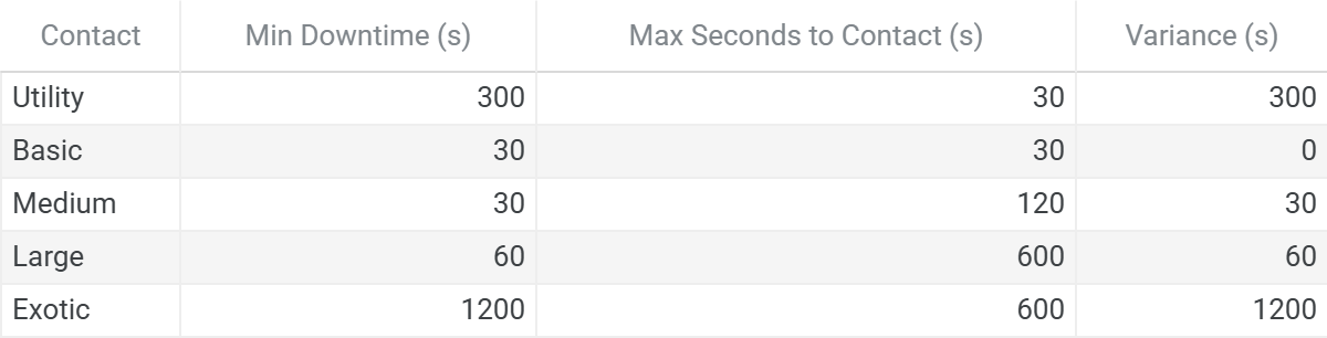
| Position | Field                  | Data Type |
|----------|------------------------|-----------|
| 0-15     | MIN_DOWNTIME           | UINT_16   |
| 16-31    | MAX_SECONDS_TO_CONTACT | UINT_16   |
| 32-47    | VARIANCE               | UINT_16   |
Stopwatches
Five stopwatches are added to the system—one per tracking dish. Each is driven by its corresponding tracking IC, which toggles stopwatch power when the contact expires. The power calculator reads the elapsed time to determine how long the current contact window has been active.
Available Charge
The maximum energy required to complete interrogation is:2
Where:
Pcontact — minimum watts to contact, read from the tracking dish
Tmax — maximum seconds to contact, from contact configuration
rinterrogation — current interrogation progress, a ratio from 0 to 1
If the battery’s current charge is less than Emax, the contact is marked infeasible and the result is set to infinity.
Ratio Derivation
The power ratio is computed in three stages. Each stack represents a feasibility zone — guaranteed, adjustable, and uncertain. The following variables are derived from contact specifications and system state before the calculation begins.
Base power level is the minimum power required to resolve the signal within a single tick:
WattsToResolve is read from the manifest dish signal data. This formula is derived from the resolution time model documented in Signal-Domain Contact Acquisition.
Base power ratio normalizes the base power level against maximum dish power:
Contact time is the time required to complete interrogation at the base power level:
Age (age) is the time since the last contact expiration, read from the stopwatch assigned to the tracking dish.
Movement time (tmove) is the estimated dish travel time, derived from the movement calculator and vertical displacement.
Weather event time (tweather) is the time until the next weather event, if imminent. Ships cannot land during weather events.
# Minimum TTL
TTL = MinDowntime + Lifetime - t_move - age
TTL = min(TTL, t_weather) # clamp weather if imminent

# Guaranteed: use base power if sufficent
if t_contact <= TTL:
  return r_base

# Adjustable: scale to maximum power
t_contact *= r_base
if t_contact <= TTL:
  return t_contact / TTL

# Uncertainty: evaluate risk based on variance
if t_contact > t_weather:
  return infinity

t_contact -= TTL
if t_contact > Variance:
  return infinity

return 1 + t_contact / Variance
A4. Reference
Reddit. Trader Contact Dish Alignment — Manual. https://www.reddit.com/r/Stationeers/comments/1r05zdo/trader_contact_dish_alignment_manual/
Stationeers Wiki. Kit (Satellite Dish). https://stationeers-wiki.com/Kit_(Satellite_Dish)
Steam Discussions. No Plane-Traders?! https://steamcommunity.com/app/544550/discussions/0/691994126364723362/
Stationeering Systems. Signal-Domain Contact Acquisition. https://stationeering.substack.com/p/dish-signal-acquisition
Stationeering Systems. Lunar Trade Economics. https://stationeering.substack.com/p/lunar-trade-economics
YouTube. IC10 Tutorial 17B: Dish Stack Instructions, Trader Inventory.
Acknowledgements
Special thanks to ShadowDrake and StormCircuit for their assistance on the Stationeers Discord.
Content developed in collaboration with Anthropic’s Claude, used for technical documentation structure, engineering analysis, and editorial refinement.
Found in Stationeers/rocketstation_Data/StreamingAssets/Data/tradeables.xml
Medium dish positional coordinates are not directly equivalent to small and large dish coordinates. This discrepancy may introduce a small error in energy consumption estimates for contacts tracked by medium dishes (Large and Exotic). The practical impact on call-down success is minimal — the available charge check uses conservative maximum values — but operators might observe slight inefficiencies in power consumption for these types.