
Note for independent readers: This document assumes prior familiarity with the architectural principles and subsystems outlined in the broader Stationeering Systems framework. Readers seeking system-level rationale or integration context are advised to consult the foundational document Signal-Domain Contact Acquisition for comprehensive design overview.
Prerequisites
Established a scalable power grid (see Solar Power Infrastructure)
Basic understanding of electrical networks
Ability to read, write, and flash IC10 programs onto controllers
Objectives
Locate all available contacts before they expire
Constraints
Coordinates must be within 2°
Up to one contact per slot (Utility, Basic, Medium, Large, Exotic) is visible at any time
Materials and Components
Fabricated Components
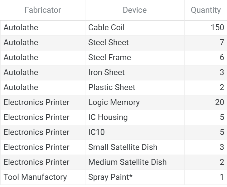
* Spray paint colors: 1 Green
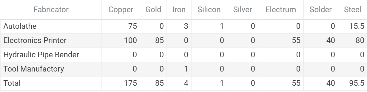
Total Ingots
Raw Ores
This chart format is standardized across the series. See the full legend in Atmospheric Recovery on the Moon, Appendix A11. Bill of Materials.
# Ores

| Ore     | Stack Qty |
|---------|-----------|
| Coal    | 2         |
| Copper  | 4         |
| Gold    | 3         |
| Iron    | 9         |
| Lead    | 1         |
| Silicon | 1         |
| Silver  | 1         |

# Ingots

- Copper →
  - Copper: 2/2/0/0
- Gold →
  - Gold: 0/2/0/0
- Iron →
  - Iron: 1/0/0/1
- Silicon →
  - Silicon: 1/0/0/0
- Steel →
  - Coal: 1/1/0/0
  - Iron: 3/3/0/0
- Electrum →
  - Gold: 0/1/0/0
  - Silver: 0/1/0/0
- Solder →
  - Iron: 0/1/0/0
  - Lead: 0/1/0/0
Power Infrastructure
The power and data networks for all tracking infrastructure are intentionally segregated. Power connections are grouped by functional subsystem—tracking and, eventually, traffic control each maintain their own supply networks. Data connections, by contrast, form a single unified network spanning all subsystems, ensuring that controllers, hangars, and dish assemblies can communicate across the full installation regardless of power topology. This separation allows each functional group to manage its own power independently while preserving a coherent data fabric as the build expands.
Installation
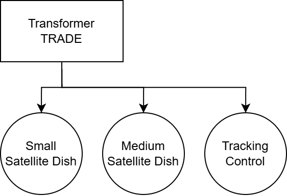
Install a dish for each contact type
Each dish is allotted 4 Logic Memory (Contact, Watts, Timeout, Downtime) and 1 IC Housing
Connect separate cables for power and data connections
Logic Initialization and Deployment
Tracking Controller
Locks onto a contact’s position.
Functional Overview
Performs a full-sky scan to isolate the contact id
Divides the scan region into nine proximity areas, using a timeout to narrow the search range.
Locks the final position by sampling neighboring points and approximating horizontal and vertical coordinates
Hardware Interface
d0: Dish
d1: Contact Slot Index Setting
d2: Minimum Watts Visible Setting
d3: Proximity Timeout Setting
d4: Downtime Setting
Configuration Parameters
- TargetSignalStrength (Maximum locked Signal Strength): 2
- AzimuthPeriod (Horizontal distance traveled for full sky scan): 1620
- ScanStepSize (Horizontal distance traveled per scan step degrees): 10
- ScanRatio (Scan detection power ratio): 0.2
- RefineRadius (Radial distance for proximity detection): 15.307
- RefineAngle (Angular step size for proximity detection): 45
Device Mapping
| Contact | Dish   | Slot | Watts | Timeout | Downtime |
|---------|--------|------|-------|---------|----------|
| Utility | Small  | 0    | 0     | 0       | 300      |
| Basic   | Small  | 1    | 0     | 0       | 30       |
| Medium  | Small  | 2    | 20    | 4.5     | 30       |
| Large   | Medium | 3    | 250   | 8       | 120      |
| Exotic  | Medium | 4    | 100   | 8       | 1200     |
Deployment Checklist
Confirm the following before activating any logic-controlled systems. This ensures that the IC program is properly mapped.
Power System Validation
Toggle on and off each dish individually to ensure power connectivity.
IC10 Chip Installation
Install the IC10 program into the logic-capable device. Update the device inputs on the IC Housing hardware to map to the devices that the controller should manage.
Final Hold
Do not turn on controller until full startup sequence has been completed and all systems are confirmed.
System Activation and Handoff
System components, logic devices, and power and data domains are now installed and configured. The system is structurally complete, and control logic is staged for deployment.
However, final activation must not proceed until all runtime behaviors have been individually validated and the Readiness Procedure is complete.
Final Preconditions for Runtime Handoff
The system must meet the following conditions before control can be handed off to automated logic:
All IC10 programs are loaded onto the connected computer
Logic files should be saved and flashed with the controller off, allowing for isolated verification of supporting systems.Power and Data are isolated networks
Data connections will be shared across all trade infrastructure, while power connections will be grouped by functional subsystem
Proceed to: System Readiness Plan
Next Steps
Contact acquisition is the first step toward automated trade and the foundation for economic expansion. This installation allows for continuous hemisphere coverage across all contact slots with position data ready for handoff.
This foundation enables expansion into the following domains:
Traffic Management — Landing infrastructure and dish handoff sequencing must operate in concert to move ships safely through the facility. The position data produced by the tracking layer serves as the input to this coordination. This module will cover large dish handoff and contact interrogation, and the logic governing port ingress and egress.
Pressurized Hangars — Accommodating contacts that require a breathable environment introduces significant infrastructure complexity beyond basic landing operations. This module will cover atmospheric mix storage for rapid compression and decompression cycles, gas recycling integration with existing life support systems, specialized access gated on environmental state, and automatic hangar activation based on incoming trader type.
Trade and Inventory — With contacts acquired and ships directed to berth, the final layer is knowing what to call and when. Inventory state drives contact selection, ensuring the port requests ships based on actual supply needs rather than availability alone. This module will cover inventory tracking, demand-driven contact calling, and the systems that move cargo in and out of the port.
Content developed in collaboration with Anthropic’s Claude, used for technical documentation structure, engineering analysis, and editorial refinement.