
Power II: Scaling Beyond Centralized Infrastructure
Migrating to priority-based power distribution for graceful degradation
Note for independent readers: This document assumes prior familiarity with the architectural principles and subsystems in the broader Stationeering Systems framework. Readers seeking system-level rationale or integration context are advised to consult the foundational document Microgrid Architecture for Resilient Power Systems for comprehensive design overview.
Prerequisites
Established a scalable power grid (see Solar Power Infrastructure)
Basic understanding of electrical networks
Ability to read, write, and flash IC10 programs onto controllers
Objectives
Automate the controlled shutdown of base systems during power shortages
Classify subnetwork priorities so that lower priority systems are shed first and higher priority systems remain online longer
Strategically migrate systems onto the new distribution while minimizing overall downtime
Constraints
Need to be able to reassign network priorities without major cable overhaul
Implementation Context
This implementation demonstrates migrating a lunar base from hub-based power distribution to a hierarchical microgrid architecture. The facility currently operates nine active systems currently powered through a single centralized network. The migration strategy prioritizes minimizing downtime while establishing zone-based allocation and load management capabilities.
Build Duration
Completion of this build significantly exceeds the typical 2-hour module format used in most guides. The complete migration described here took approximately 11 hours:
Initial region, zone, and switchboard installation: ~2 hours
Distribution line installation: ~1 hour per system (9 systems total)
Operators can break the migration into multiple sessions, installing regional infrastructure in one session and migrating systems incrementally across subsequent sessions. Each system migration is independent once zone infrastructure exists, allowing flexible scheduling around operational demands.
Why Now?
The base has reached an inflection point where power architecture becomes critical to continue operation and expansion.
Basic survival established: Life support, atmospheric processing, and agriculture are stable. Implementing hierarchical power distribution earlier would have diverted critical time from establishing these survival foundations. The 11-hour investment in infrastructure improvement is now affordable.
Logistical complexity threshold: Nine active systems represent the point where centralized hub-based distribution creates management overhead. Adding each new system requires increasingly complex routing decisions, cable management, and failure risk assessment. Without structured allocation, these growing pains will compound with every additional system.
Downtime risk mitigation: As the base scales, unplanned power failures increasingly threaten crew safety. A single power shortage currently affects all systems simultaneously — life support, access control, and fabrication all fail together. Priority-based load shedding ensures critical systems stay online during shortages, protecting crew health and safety while allowing non-essential systems to gracefully degrade.
Delaying this migration means either accepting escalating downtime risk or constraining base expansion to avoid power management complexity. Implementing structured power distribution allows for continued safe growth.
Materials and Components
Per Region:
- 1 Area Power Control
- 1 IC Housing
- 1 IC10
- Cable Coil (Heavy)
- Cable Coil
Per Zone:
- 1 Transformer (Md/Lg)
- 1 Area Power Control
- 1 IC Housing
- 1 IC10
- 2 Logic I/O
- Cable Coil (Heavy)
- Cable Coil
Per Subnetwork:
- 1 Transformer (Sm/Md)
- 1 Sign
- Cable Coil
- Cable Coil (Heavy)
- Iron Walls
- Ladders (optional)
Example
The power grid migration shown uses the following materials:
Region & Zone Controller Installation
The network containing the battery array will be referred to as the regional network.
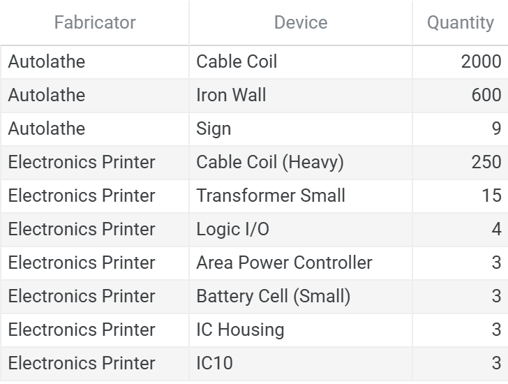
Region Control Setup
Install the Area Power Controller
Place APC and IC Housing devices
Connect APC power output to IC Housing power connection
Connect APC power input and IC Housing data connection to the regional network
Insert a small battery cell into the APC
Leave APC off for now
The regional controller allocates power to connected zones. The IC Housing draws power for the APC while communicating the on the regional network.
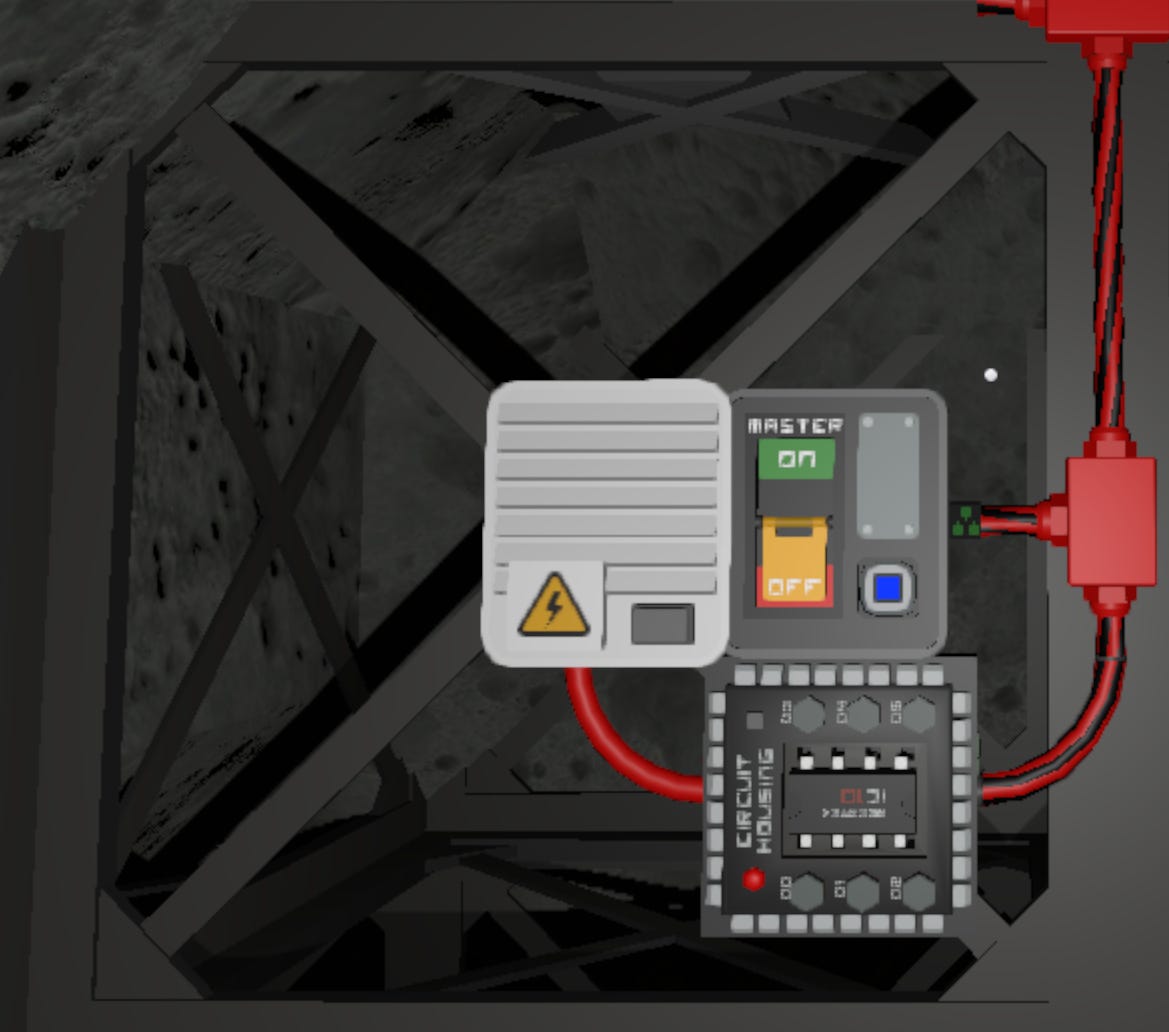
Zone Control Setup
Install the Zone Transformer
Connect transformer power input to regional network
Place APC and IC Housing devices
Connect APC power output to IC Housing power connection
Connect APC power input and IC Housing data connection to the zone network
Insert a small battery cell into the APC
Leave APC off for now
The zone controller calculates the requested potential of the zone and stores it on the IC Housing “Setting,” while also shedding subnetworks if there is insufficient power allocated to the zone.
Install Logic Reader (Requested Potential):
Connect input to zone network
Connect output to regional network
Connect power to the same power output of the APC that supports the region controller
The logic reader retrieves the requested potential from the zone controller and exposes this data to the regional network.
Install Logic Mirror (Zone Transformer):
Connect input to zone network
Connect output to regional network
Connect power to the same power output of the APC that supports the region controller
Critical: Both logic devices must draw power from the region APC. This ensures that the region controller can gather network information and restore shed loads even when zones are powered down.
Zone Configuration
Update the label to both the transformer and logic mirror (i.e. A-1.0: Sector A, Region 1, Zone 0)
Assign the transformer to one of the device pins on the region controller (lower pin index = higher priority, shed last)
Update the label to the logic reader to match the label of the transformer
Power on the zone transformer
Set transformer Setting to Maximum
Setting the transformer to maximum ensures migrated systems operate at full parity with existing hub-based system before implementing load shedding logic.
Repeat for Additional Zones: Repeat steps 2-5 for each zone in the region.
Switchboard & Subnetwork Installation
The switchboard is the physical infrastructure where all six zone transmission lines converge, providing connection points to the subnetwork. Each subnetwork position on the switchboard has access to all six zones through vertical cable stacking, enabling zone reassignment by moving a transformer between cable heights.
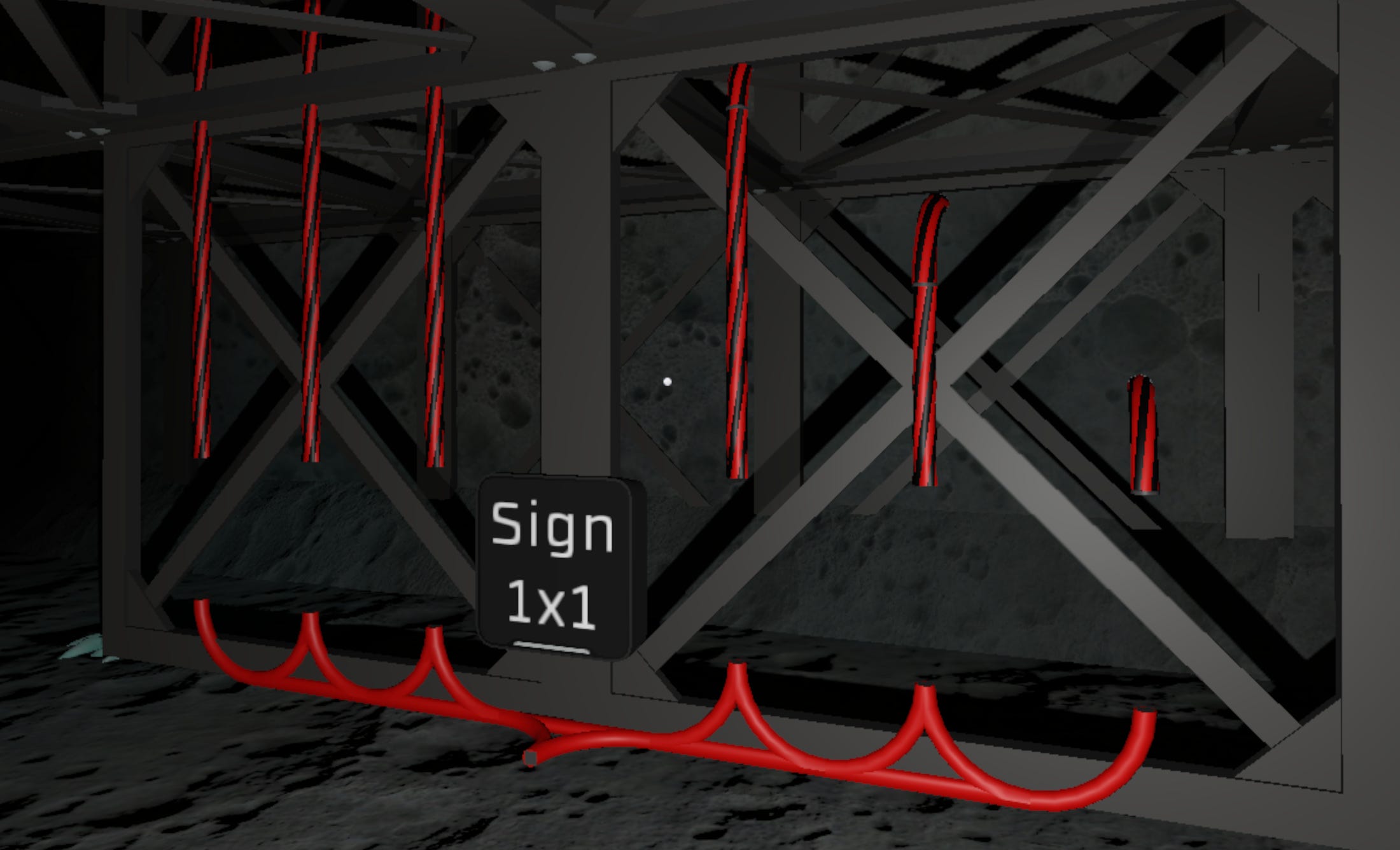
Switchboard Layout
Create Zone Transmission Lines:
Install six parallel heavy cable runs (one per zone priority)
Space vertically at 0.5m increments:
Zone 5: 0.5m height
Zone 4: 1.0m height
Zone 3: 1.5m height
Zone 2: 2.0m height
Zone 1: 2.5m height
Zone 0: 3.0m height
Create Subnetwork Connection Points:
For each subnetwork position, create vertical spacing between zone cables and subnetwork cables (0.5m gap)
Install regular cable at each zone height
Connect all six cables together at this position to create the subnetwork distribution bundle
Install Cross-Connection Cables: Behind the zone transmission lines, run heavy cables orthogonally to connect lines at the same height together. These cross cables link individual subnetwork connection points to form complete zone networks.
Subnetwork Connection
Install Transformer and Assign Zone:
Place small transformer in the 0.5m gap between chosen zone cable and subnetwork distribution bundle
Connect transformer to the zone transmission line (e.g., Zone 1 cable at 2.5m height)
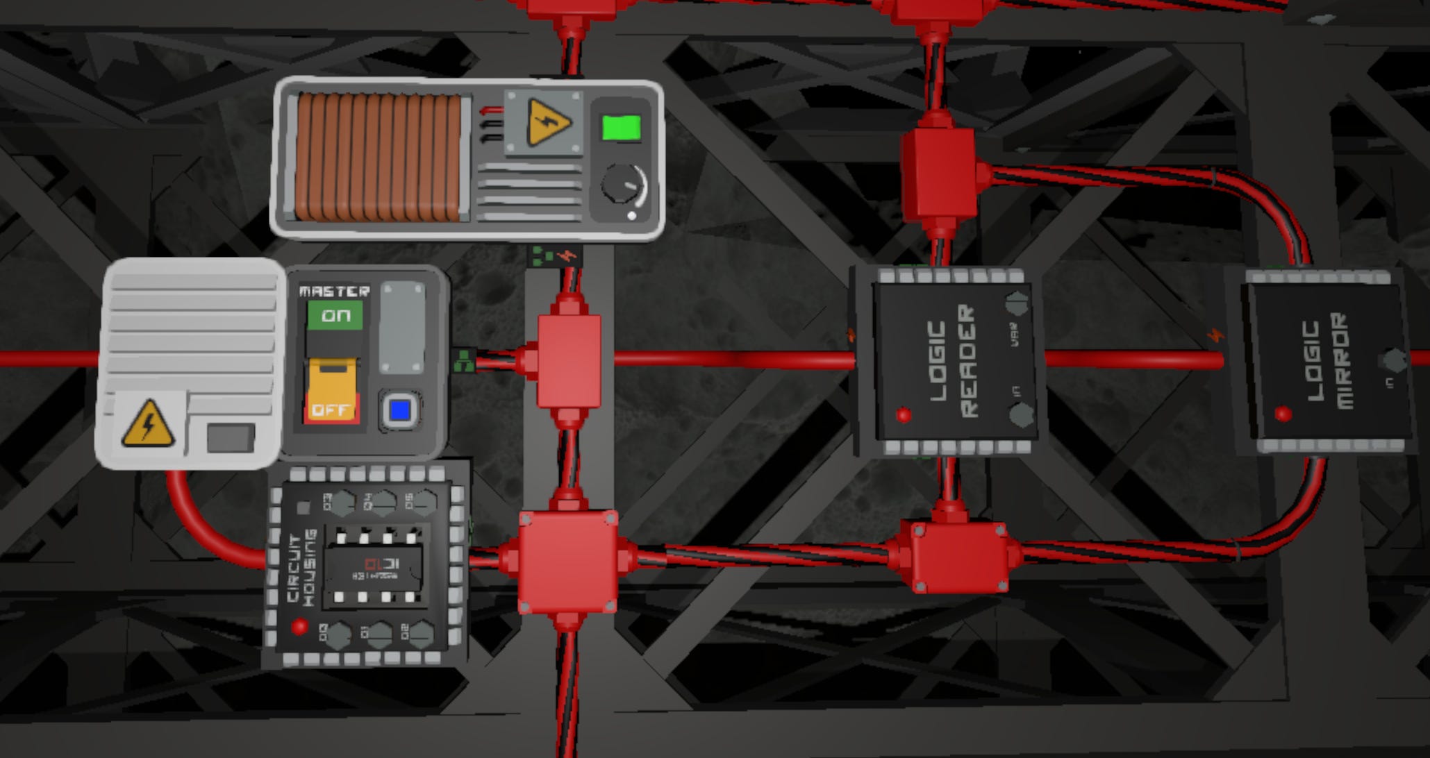
Label Subnetwork:
Attach sign displaying the network name and power setting. This serves as a reference for future zone reassignment.
Update the transformer label to match the displayed name and the transformer setting to match the displayed power setting
Subnetwork Initialization:
Assign the transformer to one of the device pins on the zone controller (lower pin index = higher priority, shed last)
Turn on the transformer. This step is not required if the zone controller is already operational. As subnetworks are assigned, power will be allocated if capacity is available.
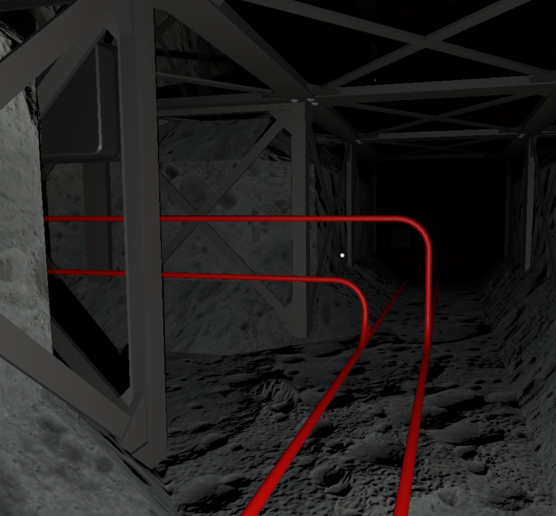
Distribution Line Routing
Create tunnels beneath base infrastructure for cable routing. Run 2-3 distribution lines per tunnel to avoid congestion.
For longitudinal runs (primary direction through base), run cables along the tunnel floor
For lateral runs (perpendicular connections), run cables along tunnel walls
At junctions: establish a standard (near wall or far wall) and apply it consistently throughout the facility
Mount lateral cables above the ground to avoid intersection with longitudinal floor cables
Surface cables at equipment connection point and connect equipment to power input
Logic Initialization & Deployment
Zone Controller
Calculates the requested allocation of characterized and uncharacterized loads and distributes power to subnetworks in priority order.
Functional Overview
Computes the required power from all area power controllers in the zone
Computes the requested power from all subnetworks in the zone
Activates or deactivates subnetworks based on the zone’s potential power and priority
Priority is determined by the pin assignment of the subnetwork: lower pin index = higher priority
Hardware Interface
d0..d5: Subnetwork Transformers
Configuration Parameters
- BasePower (Transformer Base Power W): 10Device Mapping
Area Power Control: Monitors the zone potential and calculates power required for uncharacterized loads
Region Controller
Monitors available charge and power usage and allocates power budgets to connected zones in priority order.
Functional Overview
Tracks the exponential moving average of the ratio of power consumed over total requested potential
Computes the available power budget to distribute to zones
Distributes power budget to all registered zones based on priority and requested amount
Hardware Interface
d0..d5: Zone Transformers (Mirrored)
Hardware Labeling
Each connected transformer requires a matching logic reader with an identical label to retrieve the zone’s requested potential. The controller uses these paired labels to distribute available power budget to zones.
Example:
Transformer (Logic Mirror) labeled
A-1.0Requested Potential (Logic Reader) labeled
A-1.0
Configuration Parameters
- Period (Generation offline period s): 600
- Alpha (EMA learning rate ticks): 3600
Device Mapping
Area Power Control: Calculates power required for uncharacterized loads
Battery/Battery Large: Battery array of stored energy for the region
Logic Reader: Provides the requested potential of a zone
Deployment Checklist
Confirm the following before activating any logic-controlled systems. This ensures that the IC program is properly mapped.
Device Labels
Makes sure that zones and subnetworks are labeled and properly mapped.
Power System Validation
Power on Zone and Region APCs
Turn on all logical devices except for the controllers
IC10 Chip Installation
Install the IC10 program into logic-capable device. Update the device inputs on the IC Housing hardware to map to the devices that the controller should manage.
Final Hold
Do not turn on controller until full startup sequence has been completed and all systems are confirmed.
System Activation & Handoff
System components, logic devices, and power domains are now installed and configured. The system is structurally complete and control logic is staged for deployment.
However, final logic activation must not proceed until all runtime behaviors have been individually validated and the Readiness Procedure is complete.
Final Preconditions for Runtime Handoff
The system must meet the following conditions before control can be handed off to automated logic:
All IC10 programs are loaded onto the connected computer
Logic files should be saved and flashed with the controller off, allowing for isolated verification of supporting systems.All zones are assigned a priority and mapped to the region
Every zone transformer must be mapped to a pin on the region controller.All existing systems are migrated and assigned a zone and priority
Every subnetwork must be connected through the switchboard with functional distribution lines to equipment. Legacy hub-based power connections should be disconnected and verified inactive.Zone transformers operate at maximum setting: All zone transformers must be set to maximum (no load shedding) to ensure that migrated systems operate at parity with the previous hub-based configuration.
All subnetworks power on successfully: Verify each migrated system draws power through its new distribution line and operates normally before enabling automated allocation logic.
Proceed to: System Readiness Plan
Next Steps
With microgrid power distribution established, the base now has priority-based load management, graceful degradation under constraints, and pre-emptive capacity monitoring. This infrastructure provides resilient power allocation that scales with facility complexity.
This foundation enables expansion into the following domains:
Trade Systems — Lunar resources provide most ores and ices through mining, but certain agricultural input (seeds, eggs) require external acquisition. Future modules will address trade station integration, automated purchasing systems, and inventory management for externally-sourced materials.
Advanced Agriculture — Closed-loop resource management becomes critical for operational efficiency. The current operator-managed agriculture system supports small-scale food production, but larger facilities require integrated water recycling, atmospheric gas replenishment (Carbon Dioxide, Oxygen), and waste processing systems. Future modules will address harvest systems, fertilizer production, and closed loop integration that reduces dependency on external resource inputs as resource demands grow.
Fuel Systems and Automated Smelting — Rocket fuel production and advanced manufacturing require high-temperature systems that introduce fire risk and volatiles management challenges. The power distribution system established here provides capacity for energy-intensive smelting operations. Future modules will address fuel production workflows, furnace automation, combustible materials handling, and thermal safety protocols for high-temperature operations.
Content developed in collaboration with Anthropic’s Claude, used for technical documentation structure, engineering analysis, and editorial refinement.